MM8000 MP4.
Data and design subject to change without notice. / Supply subject to availability. © 2007 Copyright by Siemens Building Technologies AG We reserve all rights in this document and in the subject thereof.
Table of contents About this document...............................................................................................2 Definitions of terms.................................................................................................5 Building Technologies Fire Safety & Security Products 1 1.1 1.2 1.3 Introduction .............................................................................................6 Overview of OPC connectivity in MM8000 .........................................
About this document Purpose of this document This manual is a guide to the configuration procedures for the integration of OPC servers into the MM8000 system. It is specifically for those individuals responsible for the commissioning of the management station, such as technical project managers, engineers, and commissioning personnel.
Reference documents The most recently released documentation for customers can be found in the STEP Documentation Repository System released at SBT FS for end-users via the STEP Web Client interface at the following address: https://intranet.sbt.siemens.com/dbcom/en/db_porta/client.asp The following describes one way to search and find a document: 1. Click on the "STEP WEB Client" image: 2. Choose "04 Fire -3F" from the "Product Segment" box and select “Activate filter”. 3.
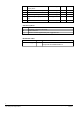
048 Network, Fire, and Intrusion Connectivity Guide A6V10062425_a 06.2007 MP4.10 048 Access Control Connectivity A6V10062451_a 06.2007 MP4.10 048 Video Connectivity A6V10062457_a 06.2007 MP4.10 048 Graphical Map Configuration A6V10062441_a 06.2007 MP4.10 022 Graphical Map Config. Quick Refer- 008906_b ence 06.2006 MP3.20 016 Migration from DMS7000 06.2007 MP4.10 A6V10062443_a Standard symbols Italics „“ (...
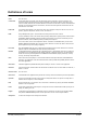
Definitions of terms Class See “Item class” Control unit The physical panel (for example, CS11 fire subsystems) that is connected to a group of detectors. The control unit receives messages from and sends commands to the detectors. When a control panel is connected to a DMS, it behaves as a translator between the detectors and the DMS. It receives commands from the DMS, and communicates them to the detectors, and it receives messages from the detectors and communicates them to the DMS.
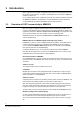
1 Introduction This is a guide to the software configuration procedures for the subsystems providing an OPC server interface. In addition, the SIMATIC S7 connectivity to MM8000 via OPC is discussed. For a complete guide to the configuration process, this manual should be used with the MM8000 Installation, Configuration, and Commissioning manual (document no.A6V10062413) and with the DMS8000 Connectivity Guides for 1.
1.2 Generic subsystems via OPC MM8000 systems can integrate safety and security control units by applying the OPC connectivity functions. A generic type of subsystem - including safety, security, and general-purpose objects - is available in the Composer environment, and can be connected to the OPC server via a specialised MM8000 driver (NS8019). The configuration of generic subsystems is presented in section 2 on page 8. 1.
2 2.1 Configuration of generic OPC subsystem Overview The entire configuration related to control units connected to MM8000 via an OPC server is defined in Composer. The OPC configuration in MM8000 includes 3 main logical steps: 1. Definition OPC items provided by the OPC server In Composer, MM8000 can support an OPC Driver (NS8019) that can connect to one or more OPC servers.
2.2 OPC subsystem configuration 2.2.1 Configuration checklist Verify that you have satisfied the items needed in the first checklist before proceeding to the configuration procedure that follows. ITEMS NEEDED FOR CONFIGURATION 2.2.2 OPC server – The OPC Server name (ProgID ). – The PC name or IP address of the machine where the OPC server runs. OPC items – OPC items list -- or-- CSV file (strongly recommended) including such a list.
2. In the menu General purpose (Fig 2), select the ‘Generic OPC’ subsystem to add the new node (Fig 3). Fig 2 ‘General purpose’ icon Fig 3 Adding a generic OPC subsystem The new OPC unit node appears in the destination folder Note: By default, the node will be named “Generic OPC #1”, you can customise the Description text by clicking the name, typing F2, and then entering a new text. Linking the new subsystem to the OPC driver 1. Select the new OPC subsystem node. 2.
Configuring the OPC server The link node between the subsystem and the OPC driver allows defining the list of OPC items to handle. 1. Click the link node and select the ‘Node’ tab. On the right, the OPC configuration form appears (Fig 5). Fig 5 Accessing the OPC configuration form In the form, the ‘OPC Server Connection properties’ section permits to define the computer and the name of the OPC server providing the field information for MM8000. 2.
– Importing a CSV file, which includes the basic information of all items (recommended) – Browsing in the Server address space (assuming the Server can support this optional feature) and selecting the required items – Entering the OPC items manually Configuring the OPC items: option 1, importing a CSV file Using the OPC server software tools and/or office applications, you need to generate a CSV file that contains the OPC items to handle.
The DMS8000 OPC class to apply for treating the OPC data (optional, but recommended) OPC classes are discussed in section 4 on page 29. Note that, if the CVS file does not include the class information, this needs to be configured manually as described on page 15 (“Configuring the OPC item classes …”). – Select the corresponding column in the three fields on the top of the window (Fig 9). Only the first column is mandatory to execute the import. After the selection, press Next to proceed.
Fig 11 OPC items imported Configuring the OPC items: option 2, browsing the OPC server space Alternatively, you can browse in the OPC server address space and select the required items (the server must support the navigation and view function). – Select the ‘Browse' button (Fig 12) in the ‘Server address space’ section of the form Fig 12 Selecting the OPC server browsing – A new window shows up (‘Data Access OPC Server Address Space’), press ‘Connect’ to start browsing into the server data (Fig 13).
Fig 14 Browsing the server space and selecting the OPC items Configuring the OPC items: option 3, manual setup As last option, you can also entering the OPC items manually: a folder and a ‘Tag’ icon are available in the OPC link node as shown in Fig 15.
4. Continue with the next item until the end. Fig 16 Selecting the OPC item class Be informed that OPC item classes can be easily imported, along with the OPC item list, from a CSV file (see page 12). For more general information about MM8000 OPC item classes and how to configure them, please refer to section 4 on page 29. Checking OPC items The configured OPC items can be validated in order to make sure that the OPC server is actually supporting all the linked items.
Fig 18 A B C D E F G H Data points Add a generic folder Add a generic object Add an output point Add an input point Add a door point Add a window point Add a fire zone point Add an intrusion zone point Save as Composer templates (menu: Tools Templates Save as) and then reuse data structures or entire subsystems that you need to insert frequently. Fig 19 Adding data points (example with a simple intrusion unit settings) Linking the OPC subsystem to the driver 1.
Fig 20 Linking OPC items and data points You can link more than one OPC items to the same MM8000 data points as long as the associated item classes can consistently cooperate to convert multiple OPC information into the same point. 18 Building Technologies Fire Safety & Security Products MM8000 OPC Connectivity Configuration Guide 06.
3 3.1 Configuration of SIMATIC S7 Overview SIMATIC S7 is the key family of PLC products of the Siemens A&D division. In MM8000 you can integrate the S7 PLC units via an OPC server. The configuration is very similar to the one described above for a generic OPC subsystem. As discussed more fully in section 2.1 above, the configuration includes three logical steps: 1. Add the OPC Driver (NS8019), and define links to OPC server and items 2. Add the S7 subsystem and the related points 3.
Fig 21 Adding the OPC driver 3. Click on the OPC driver icon in the icon toolbar (Fig 21) The new OPC driver node appears in the station folder Note: By default, the node will be named “OPC Driver #1”, you can customise the Description text typing in a new name. Adding the folder for the OPC subsystem Optionally, create a folder for the S7 unit connected via OPC server. Adding the OPC subsystem node 1. Select the destination folder. 2.
Fig 24 Linking the OPC subsystem to the corresponding driver When the link is established, a new node appears on the structure tree, just below the driver node, and it takes the same name as the subsystem node. Configuring the OPC server The link node between the subsystem and the OPC driver allows defining the list of OPC items to handle. 1. Click the link node and select the ‘Node’ tab. On the right, the OPC configuration form appears (Fig 25).
Fig 26 Selecting the OPC server The server can run both on local PC (click Local Host) or networked computers (click Network Neighborhood and then navigate until you reach the server computer). 3. Select the computer name in the list and then click OK. Note that you will not see the actual OPC server but only the computer names. Alternatively, you can directly enter the PC’s name or IP address in the corresponding field.
Fig 28 Step 1 of Import Wizard: separation character and starting line – Next, you can identify the columns to import in the file (Fig 29). Three types of information can be imported; namely: Full Tag Name, i.e. the OPC item identifier (mandatory) A description text associated to the OPC item (optional, but recommended) The DMS8000 OPC class to apply for treating the OPC data (optional, but recommended) OPC classes are discussed in section 4 on page 29.
Fig 30 Step 3 Import Wizard: check selection and finish In a short while, the OPC items will be imported, thus populating the Composer tree below the OPC driver link (Fig 31). Note that, although you may customise the OPC items in Composer by adding, renaming or deleting objects, we recommend you to keep the CSV file updated first and then import it again.
– A new window shows up (‘Data Access OPC Server Address Space’), press ‘Connect’ to start browsing into the server data (Fig 33). Fig 33 Connecting to the OPC server – In the 'Server Address Space’ section, the left section show all the existing items. You can navigate and select an entire folder (‘Add all tags’) or a single node (‘Add tags’) to add items for MM8000 to handle. Note that selected items are shown in bold. – Select all items required, then click OK.
Fig 35 Selecting the OPC item class Be informed that OPC item classes can be easily imported, along with the OPC item list, from a CSV file (see page 22). For more general information about MM8000 OPC item classes and how to configure them, please refer to section 4 on page 29.
Checking OPC items The configured OPC items can be validated in order to make sure that the OPC server is actually supporting all the linked items. This verification can be performed using the “Validate” button in the Advanced setting section of the OPC driver link node (see Fig 25 above). Proceed as follows: 1. Select the OPC driver link node node 2. Click “Validate” in the “Advanced” setting 3. In the windows that appears, click “Connect” and then “Start” 4.
Fig 37 Adding data points (example with a simple intrusion unit settings) Linking the OPC items to the corresponding data points 1. Expand the folder with OPC items (Tags) 2. Expand the folder with OPC subsystem and points 3.
4 OPC item classes This section described an advanced configuration function, which may not needed if an appropriate data set of OPC item classes is installed in Composer. If in doubt, check with your technical supervisor. 4.1 Need of conversion rules OPC items can be based on various data formats. OPC standard includes several data types, e.g.: integer (I), unsigned integer (UI), real (R), Date, Boolean (BOOL), String (BSTR). Also, data types may have multiple byte lengths: e.g.
The tool opens a window that include a toolbar on the top, a large data area on the centre, and the standard ‘OK/Cancel’ buttons on the bottom right (Fig 40). Fig 40 OPCXMLeditor interface (SIMATIC S7 item classes) On the left side of the data area, one or more data sets (associated to OPC servers) are shown in a tree-based structure. For SIMATIC S7, a large set of predefined classes is given. Instead, for generic OPC units, an example of data set named ‘Example OPC server’ is provided by default.
K L Add a state life-cycle data. This is an OPC data for acquiring a state information from the field to MM8000 via the OPC server. Format type and MM8000 property are required. Supported formats are: Enumeration, Bit-mask, String, and Analog. The MM8000 property applied in this item class must be selected in a drop-down list. Add a transaction data. This is an OPC data for acquiring a transaction information from the field to MM8000 via the OPC server.
4.3.2 Item class for ‘alarm’ conditions Instead, an alarm condition with ack and reset, stored in OPC items as numeric 0, 1, and 2 value, can be converted into the MM8000 ‘Alarm’ property as illustrated in the next two images. A state life-cycle data (Fig 43) defines that OPC values 0, 1, and 2 are associated to the Quiet, Unack, and Unreset states, respectively.
5 DCOM settings for OPC communication The communication infrastructure for OPC over a network is called DCOM. DCOM (Distributed Component Object Model) is a Microsoft Windows interprocess communication framework in which client programs can request services from server programs - on other networked computers - through a defined set of interfaces. DCOM is based on the Component Object Model (COM), which provides a set of services allowing clients and servers to communicate within the same computer.
Fig 46 Component Services window Double click the Component Services and then expand the structure below it. You can now operate at machine (recommended) or at task level. In order to set the DCOM security at machine level, right click “My Computer” and select “Properties”. In the new window (Fig 47), click the “COM security” tab and consider both “Access Permissions” and “Launch and Activation Permissions” sections.
At this point, customise both “Launch and Activation Permissions” and “Access Permissions” defaults, adding the user (“MM8000_PROC” user on the OPC server PC or the OPC server user on the MM8000 PC) and setting the “allow” attributes. Fig 48 5.1 Task properties DCOM troubleshooting In case of problems in the OPC client/server communication, you can check the DCOM error logs, which require to be manually enabled for the Windows event logging.
Fig 49 36 Building Technologies Fire Safety & Security Products Event Viewer MM8000 OPC Connectivity Configuration Guide 06.
Siemens Switzerland Ltd Building Technologies Group International Headquarters Fire Safety & Security Products Gubelstrasse 22 CH-6301 Zug Tel +41 41 724 24 24 Fax +41 41 724 35 22 www.sbt.siemens.com Document no. A6V10065253_a_en Edition 06.