
Installation Instructions


3
Shields
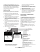
Shields for the XNET must be connected at ONE
and ONLY ONE end of the network. If you wish
to terminate the shields at the NCC-G computer,
use terminal 5 on the NCC-1F. See Figure 2.
Earth Ground
A good earth ground must be provided for proper
transient protection of the NCC-1F and the
NCC-G computer. Connect a separate ground to
terminal 6 on the NCC-1F (Refer to Figure 2).
Ground Fault Detection
The NCC-1F provides electrical isolation be-
tween the NCC-G computer and the XNET. This
allows for ground fault detection to be enabled on
the XNET. Ground fault detection is only possible
if ALL NCC-G computers in the system are
connected to XNET with an NCC-1F.
Ground fault detection must be enabled at a
NIM-1R/-1W or NIC-C. Select one and only one
NIM-1R/-1W or NIC-C in the system where the
ground fault is to be detected. You must locate
the NIM-1R/-1W in a cabinet with either an MMB,
SMB or a PSR-1. See Figure 3 for the wiring
diagram.
If the XNET is divided into multiple sections of
copper wire using fiber optic segments, ground
fault detection can be enabled at one NIM-1R/-1W
or NIC-C for each section of copper wire. Refer to
the NIC-C Installation Instructions, P/N 315-
033240 if you wish to use the NIC-C to provide
ground fault detection.
ELECTRICAL RATINGS
NCC-1F: 5 VDC @ 250mA
Network (XNET): 8V P-P, 190mA max
TB3
NIM-1R/-1W
IN TB4
NIM-1R/-1W
IN TB3
USE ONLY ONE
TB5
TB4
MOM-2
MOM-4
TB7 TB4
13 14 15
16
910
11
12
13 14 15
16
12
13 14 15
16
12
5678
+
1
1
2
2
3
4
_
+
1
2
_
Figure 3
Wiring for Ground Fault Detection