
Installation Instructions


Siemens Building Technologies
Fire Safety
P/N 315-050253-012
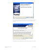
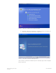
When the NCCG restarts, the NCC program will autorun and begin to
prompt you for your system configuration data as follows:
Figure 18 NCC-G/NCCWAN and NCC-GL Installation and Setup Screens
• To proceed with the installation, press the NEXT button.
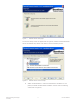
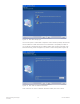
• After the NEXT button is pressed, the following screen appears, as applicable:
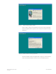
Figure 19 NCC-G and NCC-GL Node and Module Identification Screens
•The Use NIM Interface option is used with the NIM-1R to extend the NCC-
GL topography. The option allows the NCC-GL to be used on a system with
multiple nodes; however, the NCC-GL will only monitor and control one
node. In order for this option to operate, a NIM-1R card must be installed in
the node which the NCC-GL will be monitoring and controlling. The proper
module and node number for the NIM-1R must agree with the program-
ming in the MMB for the NCC-GL module.
• Enter the Node Number assignment for the NCC-G/GL system and a Node
Button label. These values can be changed later in the system dialog box.
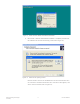
• If you do not complete this information, the following dialog box(es) appears
(as applicable) and you can not continue with the installation:
Figure 20 NCC-G/-GL and NCC-GL: MXL Unidentified Node Screens