
Installation Instructions
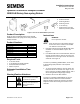


Document No. 129-367
Installation Instructions
May 13, 2021
Siemens Industry, Inc. Page 5 of 7
GDE/GLB13x, Continued
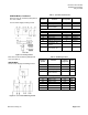
Each wire has the standard symbol printed
on it. See Table 1.
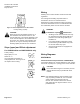
24 Vac Power Supply Floating Control.
Figure 14. Floating Control.
Table 1. 3-position Control 24 Vac.
Standard
Symbol
Function
Terminal
Designation
Color
1
Supply (SP)
G
Red
6
Control signal clockwise
Y1
Violet
7
Control signal
counterclockwise
Y2
Orange
S1
Switch A Common
Q11
Gray/red
S2
Switch A N.C.
Q12
Gray/blue
S3
Switch A N.O.
Q14
Gray/pink
S4
Switch B Common
Q21
Black/red
S5
Switch B N.C.
Q22
Black/blue
S6
Switch B N.O.
Q24
Black/pink
P1
Feedback Potentiometer
0 to 100% P1 - P2
a
White/red
P2
Feedback Potentiometer
Common
b
White/blue
P3
Feedback Potentiometer
100 to 0% P3 - P2
c
White/pink
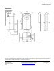
Each wire has the standard symbol printed
on it. See Table 2.
GDE/GLB16x
24 Vac Power Supply, Modulating Control
Figure 15. 0 to 10 Vdc Modulating Control.
Table 2. Modulating Control.
Standard
Symbol
Function
Terminal
Designation
Color
1
Supply (SP)
G
Red
2
Neutral (SN)
G0
Black
8
0 to 10V input signal
Y
Gray
9
Output for 0 to 10 Vdc
position indication
U
Pink
Factory installed options
S1
Switch A – Common
Q11
Black
S2
Switch A – N.C.
Q12
Black
S3
Switch A – N.O.
Q14
Black
S4
Switch B – Common
Q21
Black
S5
Switch B – N.C.
Q22
Black
S6
Switch B – N.O.
Q24
Black