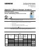
Technical Instructions Document No. 155-187P25 EA GDE/GLB-1 May 19, 2014 OpenAir™ Electric Damper Actuators GDE/GLB Series Non-spring Return Rotary 24 Vac - Modulating Control 0 to 10 Vdc Description The OpenAir direct coupled 24 Vac non-spring return rotary electric actuators are designed for modulating control of dampers.
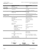
Technical Instructions OpenAir™ Non-Spring Return Rotary Electric Damper Actuator Document Number 155-187P25 May 19, 2014 Specifications Power Supply Control signal 24 Vac – Modulating Control Operating voltage (G–G0) Frequency Power consumption Input signal (Y-G0) Voltage-input 24 Vac +20%, -15% 50/60 Hz 3.3 VA 0 to 10 Vdc Input resistance >100K ohms Feedback signal Position output signal (U–G0) (GDE161.1T and GDE161.
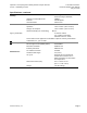
OpenAir™ Non-Spring Return Rotary Electric Damper Actuator 24 Vac – Modulating Control Technical Instructions Document Number 155-187P25 May 19, 2014 Specifications, continued Housing Enclosure GDE161.1T and GDE161.1N Material Gear lubrication Ambient conditions Agency certification conformity Miscellaneous Siemens Industry, Inc.
Technical Instructions OpenAir™ Non-Spring Return Rotary Electric Damper Actuator Document Number 155-187P25 May 19, 2014 24 Vac – Modulating Control Accessories NOTE: The auxiliary switches cannot be added in the field. Order the product number that includes this option. See Table 1. ASK76.1U: Provides connection between the actuator and conduit. NOTE: GDE161.1T Terminal Strip and GDE161.1N Post Header AMP are not compatible with the ASK76.1U. Figure 2. Conduit Adapter. ASK71.
OpenAir™ Non-Spring Return Rotary Electric Damper Actuator 24 Vac – Modulating Control Technical Instructions Document Number 155-187P25 May 19, 2014 985-133: 0 to 10 Vdc input cable 3 ft, 12 pk Accessories, Continued Figure 8. 985-134: Daisy chain cable 12 ft, 12 pk 985-135: Daisy chain cable 25 ft, 12 pk Figure 9. Figure 10. NEMA Type 4X Weather Shield. ASK75.
Technical Instructions OpenAir™ Non-Spring Return Rotary Electric Damper Actuator Document Number 155-187P25 May 19, 2014 24 Vac – Modulating Control Actuator Components, Continued GDE161.1T: The GDE161.1T uses a Terminal Strip for connection purposes rather than cable connections. Terminal Strip Figure 12. GDE161.1N: The GDE161.1N model uses a Post Header for connection purposes rather than cable connections. The Post Header AMP has two identical sets of contacts.
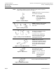
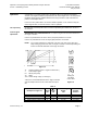
OpenAir™ Non-Spring Return Rotary Electric Damper Actuator 24 Vac – Modulating Control Operation Technical Instructions Document Number 155-187P25 May 19, 2014 A continuous 0 to 10 Vdc signal from a controller to wire 8 (Y) operates the damper actuator. The angle of rotation is proportional to the control signal. A 0 to 10 Vdc position feedback output signal is available between wire 9 (U) and wire 2 (G0) to monitor the position of the damper motor.
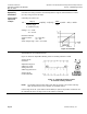
Technical Instructions OpenAir™ Non-Spring Return Rotary Electric Damper Actuator Document Number 155-187P25 May 19, 2014 24 Vac – Modulating Control Operation, continued Determine the setting needed to electronically limit the angle of rotation between 0 to 50% (0 to 45°) using a 2 to 10 Vdc input.
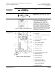
OpenAir™ Non-Spring Return Rotary Electric Damper Actuator 24 Vac – Modulating Control Dual in-Line Package (DIP) Switches GDE16x.1P GLB16x.1P Technical Instructions Document Number 155-187P25 May 19, 2014 Raise the protective cover from left to right to locate the DIP switches. See Figure 11 for the location of the cover. The factory setting is 0 (OFF).
Technical Instructions OpenAir™ Non-Spring Return Rotary Electric Damper Actuator Document Number 155-187P25 May 19, 2014 24 Vac – Modulating Control The type of actuator required depends on several factors. Sizing 2 2 1. Obtain damper torque ratings (ft-lb/ft or Nm/m ) from the damper manufacturer. 2. Determine the area of the damper. 3.
OpenAir™ Non-Spring Return Rotary Electric Damper Actuator 24 Vac – Modulating Control Manual Override Technical Instructions Document Number 155-187P25 May 19, 2014 To move the damper blades and lock the position with no power present: 1. Slide the red manual override knob toward the back of the actuator. 2. Make adjustments to the damper position. 3. Slide the red manual override knob toward the front of the actuator. Once power is restored, the actuator returns to automated control.
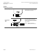
Technical Instructions OpenAir™ Non-Spring Return Rotary Electric Damper Actuator Document Number 155-187P25 May 19, 2014 Wiring 24 Vac – Modulating Control • All wiring must conform to NEC and local codes and regulations. • Use earth ground isolating step-down Class 2 transformers. Do not use autotransformers. • The sum of the VA ratings of all actuators and all other components powered by one transformer must not exceed the rating of the transformer.
OpenAir™ Non-Spring Return Rotary Electric Damper Actuator 24 Vac – Modulating Control Technical Instructions Document Number 155-187P25 May 19, 2014 Wiring , Continued Terminal Strip NOTE: Maximum wire size for the GDE161.1T is 14 AWG. GDE161.1T Figure 24. GDE161.1T Terminal Strip. Strain Relief Figure 25. GDE161.1T Wiring Diagram. Securing the wires/cabling will prevent breakage and ensure strong signals to and from the GDE161.1T model. The following is recommended: 1.
Technical Instructions OpenAir™ Non-Spring Return Rotary Electric Damper Actuator Document Number 155-187P25 May 19, 2014 24 Vac – Modulating Control Wiring, Continued Post Header AMP The GDE161.1N Post Header AMP has two sets of identical contacts as shown in Figure 27. GDE161.1N • All wiring must conform to NEC and local codes and regulations. • Use earth ground isolating step-down Class 2 transformers. Do not use autotransformers.
OpenAir™ Non-Spring Return Rotary Electric Damper Actuator 24 Vac – Modulating Control Technical Instructions Document Number 155-187P25 May 19, 2014 Wiring, Continued Post Header AMP The input cable (purchased separately) brings power and a control signal to the first actuator in a daisy chain configuration. See Figure 30 and Figure 31. CAUTION: Insert the plug into the GDE161.1N from the left to prevent damage to the cable wires. (See Figure 29) 1.
Technical Instructions OpenAir™ Non-Spring Return Rotary Electric Damper Actuator Document Number 155-187P25 May 19, 2014 24 Vac – Modulating Control Wiring, Continued Daisy Chain Configuration, NOTE: You must select either the top 3 contacts or the bottom 3 contacts. Figure 31. WARNING: Do not configure more than 12 actuators in a daisy chain at any time. Troubleshooting Start-Up/ Commissioning WARNING: Do not open the actuator. If the actuator is inoperative, replace the unit. 1.
OpenAir™ Non-Spring Return Rotary Electric Damper Actuator 24 Vac – Modulating Control Technical Instructions Document Number 155-187P25 May 19, 2014 4. Connect wires S1 and S2 to the DMM. The DMM should indicate open circuit or no resistance. 5. Stop the signal to wire 8 (gray). The DMM should indicate contact closure as the actuator shaft coupling reaches the setting of switch A. Check the Auxiliary Switch B: 1. Set the DMM dial to ohms (resistance) or continuity check. 2.
Technical Instructions Document Number 155-187P25 May 19, 2014 OpenAir™ Non-Spring Return Rotary Electric Damper Actuator 24 Vac – Modulating Control Dimensions, Continued Figure 33. GDE/GLB Actuator and Mounting Bracket Dimensions in Inches (mm). Page 18 Siemens Industry, Inc.
OpenAir™ Non-Spring Return Rotary Electric Damper Actuator 24 Vac – Modulating Control Technical Instructions Document Number 155-187P25 May 19, 2014 Dimensions, continued Figure 34. GDE161.1T and GDE161.1N Actuators and Mounting Bracket Dimensions in Inches (mm). Information in this publication is based on current specifications. The company reserves the right to make changes in specifications and models as design improvements are introduced. OpenAir is a trademark of Siemens Schweiz AG.