
User Guide


OpenAir™ Non-Spring Return Rotary Electric Damper Actuator Technical Instructions
24 Vac – Modulating Control Document Number 155-187P25
May 19, 2014
Siemens Industry, Inc. Page 7
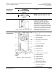
Operation
A continuous 0 to 10 Vdc signal from a controller to wire 8 (Y) operates the damper
actuator. The angle of rotation is proportional to the control signal. A 0 to 10 Vdc position
feedback output signal is available between wire 9 (U) and wire 2 (G0) to monitor the
position of the damper motor.
In the event of a power failure, the actuator holds its position. In the event that only the
control signal is lost, the actuator returns to the "0" position.
Life expectancy
An improperly tuned loop will cause excessive repositioning that will shorten the life of
the actuator.
Control signal
adjustment
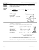
GDE/GLB163.1P and GDE/GLB164.1P: For sequencing and the electronic limitation of
the angle of rotation.
Use the Uo potentiometer to set the offset (start point) between 0 to 5 Vdc.
Use the ∆U potentiometer to set the slope (span) between 2 to 30 Vdc.
NOTE: The Y input is limited to a maximum of 10 Vdc. If the sum of the offset and
slope setting is greater than 10V, the angle of rotation is reduced providing the
feature of electronic limitation of the angle of rotation.
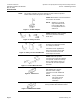
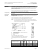
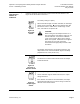
Figure 14.
Ys Actuator position (100% = angle of rotation 90°*)
Y Control input signal
Uo Offset (start point)
∆U Slope
∆Uw Active voltage range (Ys changes)
* When the mechanical limitation of the angle of rotation
and self-adapt function are ON, 100% does not equal
90°.
Setting for
10V slope
0 Vdc offset
Figure 15.
Table 2.
Examples in Figure 14
Uo
Offset
Vdc
∆
U
Slope
Vdc
Active Voltage
Range
Vdc
Ys
Actuator
Position
1. Minimum slope
0
2
0 to 2
0 to 100%
2. Limitation of rotation
5
30
5 to 10
0 to 16.7%
3. Limitation of rotation
0
30
0 to 10
0 to 33.3%
4. Setting shown in Figure 14
0
10
0 to 10
0 to 100%