
User Guide


Technical Instructions OpenAir™ Non-Spring Return Rotary Electric Damper Actuator
Document Number 155-187P25 24 Vac – Modulating Control
May 19, 2014
Page 8 Siemens Industry, Inc.
Operation,
continued
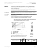
Control signal
adjustment
example:
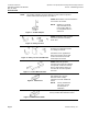
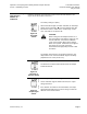
Determine the setting needed to electronically limit the angle of rotation between 0 to 50%
(0 to 45°) using a 2 to 10 Vdc input.
Calculating the value of ∆U:
Vdc
Vdc
VdcVdcUoVdc
[%]
U 16
)2
10
(
%50
%100
])[]
[10
(
[%]
Ysrotation of
angle
working
100
=−×=−
×
=∆
Settings: Uo = 2 Vdc;
∆U = 16 Vdc
Electronic limitation
angle of rotation Ys = 50% (45°)
Slope ∆U = 16V
Active voltage range ∆Uw = 2 to 10 Vdc
Figure 16. Example.
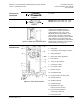
Auxiliary Switches
GDE/GLB164.1P and GDE/GLB166.1P
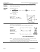
Figure 17 shows the adjustable switching values for auxiliary switches A and B.
Actuator Scale:
Clockwise
Adjustment range for
Switches A and B
Setting interval: 5°
Switching hysteresis: 2°
Actuator Scale:
Counterclockwise
Figure 17. Adjustable Switching Values
for the Dual Auxiliary Switches.
NOTE: The auxiliary switch setting shafts rotate with the actuator. The scale is valid only
when the actuator is in the "0" position on clockwise motion.
Use the long arm of the † (
AUX SWITCH ADJUSTMENT) to point to the position of switch A. Use
the narrower tab on the red ring to point to the position of switch B.