
User Guide


OpenAir™ Non-Spring Return Rotary Electric Damper Actuator Technical Instructions
24 Vac – Modulating Control Document Number 155-187P25
May 19, 2014
Siemens Industry, Inc. Page 9
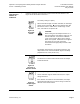
Dual in-Line Package
(DIP) Switches
GDE16x.1P
GLB16x.1P
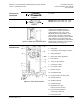
Raise the protective cover from left to right to locate the DIP switches. See
Figure 11 for the location of the cover.
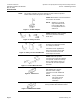
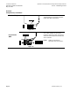
Figure 18.
Self-adapt
Switch.
The factory setting is 0 (OFF).
When mechanical angle of rotation is limited, the self-adapt
switch may be turned ON
so that the limited range will
become the new 0 to 100% for the actuator logic. In this
case, 0 to 100% is not equal to 90°
CAUTION:
When turning the self-adaptive feature on or
after the software reset with the feature on, the
actuator will enter a five-minute calibration
cycle as the actuator adjusts to the rotation
limits of the system. A software reset happens
after power on or may be caused by
electrostatic discharge (ESD) at levels of 2kV
and above.
The position output signal U is not influenced by the self-
adapt function. The 0 to 10V feedback signal U is always
proportional to 0° to 90° (or 90° to 0°).
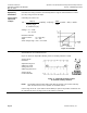
Figure 19.
Direction of
Rotation Switch.
The factory setting is clockwise.
The direction of rotation switch should match the damper
rotation movement.
Figure 20.
Output Signal
Switch.
The factory setting is direct acting.
As the clockwise angle of rotation increases, the output
voltage increases.
If the direction of rotation is counterclockwise, the output
signal switch should be set at reverse acting to match the
direction of the rotation switch.