
Installation Instructions

Der Berührungsschutz muss durch den Einbau gewährleistet
sein.
Anschlussleitung mit Schutzkontakt-Stecker
Das Gerät darf nur an eine vorschriftsmäßig installierte Schutz-
kontakt-Steckdose angeschlossen werden.
Wenn der Stecker nach dem Einbau nicht mehr erreichbar ist
muss installationsseitig eine allpolige Trennvorrichtung mit
einem Kontaktabstand von mind. 3 mm vorhanden sein.
Anschlussleitung ohne Schutzkontakt-Stecker
Nur ein konzessionierter Fachmann darf das Gerät anschließen.
Für ihn gelten die Bestimmungen des regionalen Elektrizitätsver-
sorgers.
In der Installation muss ein allpoliger Trennschalter mit mindes-
tens 3 mm Kontaktöffnung vorhanden sein. Phase- und Neutral-
(“Null-“) Leiter in der Anschlussdose identifizieren. Bei Falschan-
schluss kann das Gerät beschädigt werden.
Nur nach Anschlussbild anschließen. Spannung siehe Typen-
schild. Die Adern der Netzanschlussleitung entsprechend der
Farbcodierung anschließen: grün-gelb = Schutzleiter
<, blau =
(Null) Neutral-Leiter, braun = Phase (Außenleiter).
Nur GB und Australien
Nicht mit einem 13 A Stecker anschließen oder mit 13 A absi-
chern.
Nur Schweden, Finnland und Norwegen
Das Gerät kann auch mit dem beigelegten Stecker mit dem
Schutzkontakt-System angeschlossen werden. Dieser muss
nach dem Einbau zugänglich sein. Ist dies nicht der Fall, muss
installationsseitig wieder ein allpoliger Trennschalter mit mindes-
tens 3 mm Kontaktöffnung eingesetzt werden.
Gerät befestigen - Bild 5
■ Gerät ganz einschieben und mittig ausrichten.
■ Gerät festschrauben.
■ Der Spalt zwischen Arbeitsplatte und Gerät darf nicht durch
zusätzliche Leisten verschlossen werden.
Ausbau
Gerät spannungslos machen. Befestigungsschrauben lösen.
Gerät leicht anheben und ganz herausziehen.
en
Ú
Installation instructions
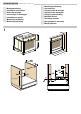
Preparing the units - Fig. 1
■ The safe operation of this appliance can only be guaranteed if
it has been installed to a professional standard in accordance
with these installation instructions. The installer is liable for
damage incurred as a result of incorrect installation.
■ Fitted units must be heat-resistant up to 90 °C, and
neighbouring unit fronts up to 70 °C.
■ Cut-out work on the units and worktop should be performed
before fitting the appliances. Remove any shavings or the
function of the electrical components may be impaired.
■ Caution during installation. Parts that are accessible during
installation may have sharp edges. Wear protective gloves to
prevent cuts
■ The power socket for the appliance must either be located in
the hatched area B or else away from the installation space.
■ A gap of 5 mm is required between the appliance and
surrounding unit fronts.
■ Secure freestanding units to the wall using a standard bracket
C.
Appliance under the worktop - Fig. 1
There must be a ventilation cut-out made in the intermediate
floor of the surround unit.
Secure the worktop to the fitted units.
If a fitted oven is to be built in under a hob, pay attention to the
hob installation instructions.
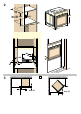
Appliance in a tall unit Figs 2+4
The appliance may also be installed in a tall unit.
There must be a gap between the intermediate floors and the
mounting wall of approx. 20 mm in order to provide ventilation
to the oven.
Only fit the appliance at a height where removing baking trays
does not present a problem.
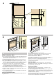
Corner installation Fig. 3
To ensure that the appliance door can be opened in the case of
corner installation, take account of dimension D. Dimension E is
dependent on the thickness of the unit front under the handle.
Connecting the appliance to the power supply
The appliance corresponds to protection class I and may only
be operated with a protective earth connection.
The appliance must be disconnected from the power supply for
all installation work.
The appliance must only be connected with the power cable
provided. Connect the power cable to the back of the appliance
(listen for the click).
A longer power cable can be obtained from the after-sales
service.
The power cable may only be replaced by a cable from the
original manufacturer, obtainable via the after-sales service.
Contact protection must be ensured by the installation.
Power cable with a plug with earthing contact
The appliance must only be connected to a properly installed
protective contact socket.
If the plug is no longer accessible following installation, an all-
pole isolating switch must be present on the installation side
with a contact gap of at least 3 mm.
Power cable without a plug with earthing contact
Only allow a licenced professional to connect the appliance. He
is subject to the regulations of the local electricity provider.
An all-pole isolating switch with at least a 3 mm contact gap
must be fitted in the installation. Identify the phase and neutral
(zero) conductor in the connection socket. Incorrect connection
may cause damage to the appliance.
only connect as per the connection diagram. See the rating
plate for the voltage. Connect the wires of the mains power
cable according to the colour coding: green/yellow = PE
conductor
<, blue = neutral conductor, brown = phase (external
conductor).
UK and Australia only
Do not connect using a 13 A plug or protect with a 13 A fuse.
Only in Sweden, Finland and Norway
The appliance can also be connected using the plug provided
which has an earthing contact system. This must still be
accessible after installation. If this is not the case, an all-pole
isolating switch must be used on the installation side with a
contact gap of at least 3 mm.
Securing the appliance Fig. 5
■ Fully insert the appliance and centre it.
■ Screw the appliance into place.
■ The gap between the worktop and the appliance must not be
closed by additional battens.
Removal
Disconnect the appliance from the power supply. Undo the
securing screws. Raise the appliance slightly and pull it out
completely.
fr
Þ
Notice de montage
Préparation du meuble - fig. 1
■ Uniquement une installation effectuée selon cette notice de
montage garantit une utilisation en toute sécurité. En cas de
dommages résultant d'une installation incorrecte, l'installateur
est responsable.
■ Les meubles d'encastrement doivent résister à des
températures jusqu'à 90 °C , les façades des meubles
attenants à des températures jusqu'à 70 °C.
■ Effectuer tous les travaux de découpe sur le meuble et sur le
plan de travail avant d'encastrer les appareils. Enlever les
copeaux, le fonctionnement des composants électriques peut
être compromis.
■ Attention lors de l'encastrement! Des éléments accessibles
pendant le montage peuvent posséder des arêtes vives.
Porter des gants de protection pour éviter des coupures
■ La prise de raccordement de l'appareil doit se situer dans la
zone de la surface B ou à l'extérieur de la zone
d'encastrement.
■ Une fente d'aération de 5mm est nécessaire entre l'appareil et
les façades des meubles attenants.
■ Les meubles non fixés doivent être vissés au mur avec une
équerre usuelle du commerce C.
Appareil sous le plan de travail - fig. 1
Le faux-plancher de la niche nécessite une découpe pour
l'aération.