
User's Manual

Automation and Drives - SCE
T I A Training Document Page 7 of 25 Module
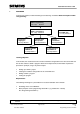
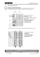
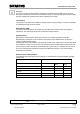
2.1 OPERATING THE CPUS 31XC
Operator control and display elements
The following illustration shows the operator control and display elements of a CPU 31xC.
The arrangement and number of elements in some CPUs differ from this illustration.
The figures show the following
CPU elements:
(1) Status and error displays
(2) Slot for the Micro Memory Card (MMC),
incl. the ejector
(3) Connections of the integrated I/O.
(4) Power supply connection
(5) 1
st
interface X2 (PtP or DP)
(6) 1
st
interface X1 (MPI)
(7) Mode selector switch
The following illustration shows the digital and analog inputs/outputs integrated on the CPU.
The figure shows the following
integrated I/Os:
(1) Analog I/Os
(2) each with 8 digital inputs
(3) each with 8 digital outputs
(4) Front connectors (front
doors are open)
f f
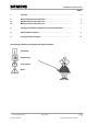
Foreword Notes
H
H
a
a
r
r
d
d
w
w
a
a
r
r
e
e
c
c
o
o
n
n
f
f
i
i
g
g
u
u
r
r
a
a
t
t
i
i
o
o
n
n STEP 7 program Testing
A5
Issue date: 02/2008 Programming the CPU 314C-2DP