
Product Overview


Technical Instructions MXG461…U, MXF461…U Modulating Control Valves
Document Number CA1N4455E-P25 with Magnetic Actuators
May 8, 2009
Page 2 Siemens Building Technologies, Inc.
Application
The MXG461...U (screwed fitting) and MXF461...U (flange fitting) valves are mixing or
straight-through valves with a factory calibrated and mounted magnetic actuator. The
magnetic actuator incorporates an electronics module for position control and
positioning feedback. Control path A → AB is closed when the valve is de-energized.
CAUTION:
The valve is suitable for straight-through normally closed or three-way
applications and may be installed only in a mixing arrangement.
The direction of flow (A → AB) must be as indicated on the valve.
The fast positioning time, high resolution and high rangeability make these valves ideal
for modulating control of chilled and hot water systems in closed circuits. Sturdy
construction makes maintenance and regular servicing unnecessary and ensures a
long service life.
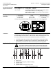
Ordering
When using a 2-1/2 inch flanged valve in a straight-through application, a blanking
flange is required for the third port. If required, order Z155/65 separately.
For screwed valves, no additional ordering is required. The components required to
create a straight-through valve are included with the valve.
Principles/
Construction
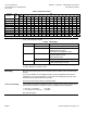
Automatic Control
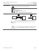
The control signal is converted by the microprocessor in the electronics module into an
output signal that generates a magnetic field in the core. This causes the only moving
part, the armature, to change its position in accordance with the interacting forces
(magnetic field, counter-spring, hydraulics, and so on). The armature responds rapidly
to any change in signal, transferring the corresponding movement directly to the control
disc, enabling fast changes in load to be corrected quickly and accurately. The valve
position is measured continuously. The positioning controller ensures an exactly
proportional relationship between the control signal and the valve stroke.
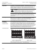
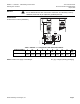
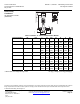
Valve Characteristic
Volumetric flow
10 [V]
10 [V]
20 [mA]
86420
2
4
100
80
60
40
20
0
[%]
y
6
12
y
y
SVAL0227R1
Control signal
Volumetric flow
10 [V]
10 [V]
20 [mA]
86420
2
4
100
80
60
40
20
0
[%]
y
6
12
y
y
Sval0012R2
Control signal
Figure 1. Equal-percentage. Figure 2. Linear.
In the event of a power failure, or if the power is switched off, the spring force closes the
valve automatically (control path ports A → AB normally closed).