
Product Overview


MXG461…U, MXF461…U Modulating Control Valves Technical Instructions
With Magnetic Actuators Document Number CA1N4455E-P25
May 8, 2009
Siemens Building Technologies, Inc. Page 7
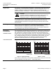
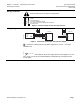
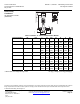
Wiring Terminals
WARNING:
Earth ground must be connected to the pipe work.
1
2
3
4
5
6
G0
G
Y
X
YF
~
Sval0011R1
YM
24 Vac
24 Vac
Control signal input
Control signal reference voltage
0 to 10 Vdc stroke signal output (position feedback)
Override control
Figure 6. Terminal Layout for Four-wire Connections.
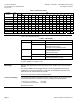
Wiring Diagram
+
1
2
3
4
5
6
U
2-10 VDC
0-10 VDC
24 VAC
4-20 mA
24
VAC
G0
G
Y
YM
X
YF
MX...461...
1
2
3
4
5
6
24
VAC
G0
G
Y
YM
X
YF
MX...461...
±
Sval00228R1
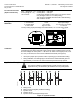
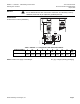
Figure 7. Connection to Controller with Four-wire Output.
U = Indication of valve position (only where required). 0 to 10 Vdc → 0 to 100%
volumetric flow
SSEN0093R1
TWISTED PAIRS
If the cables for the 24 Vac supply and the control signal 0 to 10 Vdc
(2 to 10 Vdc, 4 to 20 mA are routed separately, twisted pairs are not required for the
24 Vac cable).