
Product Overview


Technical Instructions MXG461…U, MXF461…U Modulating Control Valves
Document Number CA1N4455E-P25 with Magnetic Actuators
May 8, 2009
Page 8 Siemens Building Technologies, Inc.
Forced Control Feature
(Input Terminal YF/6)
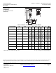
0 Vac (Bridge G0 – YF)
24 Vac (Bridge G – YF)
1 to 9 Vdc at F
Control path A → AB closed
Control path A → AB open
Continuously variable low limit control 10% to 90% volume
flow (the higher value YF of Y takes priority).
This function is available with valves with a manufacturing
date of 990701 or later.
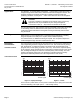
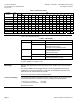
Configuration
Switches
Switch
1 Characteristic
2 Control signal
3 Volts or mA
Off
Linear
0 to 10 Vdc*
0(2) to 10 Vdc*
On
Equal percentage*
2 to 10 Vdc or 4 to 20 mA
4 to 20 mA
* Factory setting: equal percentage valve characteristic, 0 to 10 Vdc control signal.
70038c
A
B
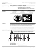
Figure 8. DIP Switches.
Calibration
The MX…461…P magnetic valves are factory-calibrated at 0% and 100% stroke. When
commissioning the valves (especially under extreme usage conditions) there may still
be some leakage via control path A → AB with a 0% stroke control signal (0 Vdc, 4 mA
or 2 Vdc). In this case, the valve can be recalibrated as follows (see Figure 8):
• Use a pin or paper clip to push the button in opening (A) in the terminal housing.
• During calibration, the LED light (B) in the electronics module will flash green for
approximately 10 seconds. The valve will be briefly closed and fully opened.
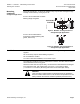
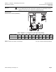
Application Example
CAUTION:
This valve is suitable for straight-through normally closed or three-way
applications only, and should only be installed in a mixing arrangement.
B
A
B
AB
B
A
A
AB
B
A
C
D E
AB
10
(min. 20 in)
x D N
AB
B
A
A
AB
Sval0014R1
A Mixing circuit
B Mixing circuit with bypass (underfloor heating)
C Injection circuit
D Diverting circuit
E Injection circuit with straight-through valve
Figure 9. Hydraulic Circuits.