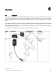
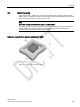
6 Antennas 6.1 Features This radio transmitter with IC ID: 267X-RF350R02 has been approved by Industry Canada to operate with the antenna types listed below with the maximum permissible gain indicated. Antenna types not included in this list, having a gain Product greaterphoto than the maximum gain indicated for thatStype, are strictly prohibited for use with this Antenna Limit distance Dimensions g 1) device. ANT 1 Up to 140 mm 75 x 75 x 20 mm .
Antennas 6.1 Features Antenna Product photo ANT 3S Limit distance Sg 1) Dimensions Up to 5 mm 50 × 28 × 10 mm (L x W x H) ANT 8 2) Up to 4 mm M8 x 1.0 x 39 mm (∅ x thread x L) ANT 12 Up to 16 mm M12 x 1.0 x 40 mm (∅ x thread x L) ANT 18 Up to 35 mm M18 x 1.0 x 55 mm (Ø x thread x L) ANT 30 Up to 55 mm M30 x 1.
Antennas 6.1 Features Note Use of the antennas in hazardous areas The antennas ANT 1, ANT 12, ANT 18 and ANT 30 are approved for use in hazardous locations. For more information, refer to the section "Use of the reader in hazardous areas (Page 149)". ANT 1 The ANT 1 is an antenna in the mid performance range and can be used to the customer's advantage in production and assembly lines due to its manageable housing shape.
Antennas 6.2 Ordering data ANT 30 The ANT 30 is designed for use in small assembly lines. In comparison to ANT 18, the maximum write/read distance is approximately 60 % larger. Due to its compact construction, the antenna can be easily positioned for any application using two plastic nuts (included in the package). The antenna cable can be connected at the reader end. 6.2 Ordering data Table 6- 1 Ordering data for antennas Article number ANT 1 incl.
Antennas 6.4 Metal-free area 6.4 Metal-free area The antennas ANT 1, ANT 8, ANT 12, ANT 18 and ANT 30 can be flush-mounted in metal. Please allow for a possible reduction in the field data values. During installation, maintain the minimum distances (a and b) on/flush with the metal. Note Reduction of range if the metal-free space is not maintained At values lower than a and b, the field data changes significantly, resulting in a reduction in the limit distance and operating distance.
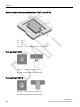
Antennas 6.4 Metal-free area Metal-free space for flush-mounted installation of ANT 3 and ANT 3S ① ② ANT 3 a = 10 mm Metal Figure 6-2 ANT 3 and ANT 3S flush-mounted in metal Flush-mounting of ANT 8 Figure 6-3 ANT 8 flush-mounted in metal The ANT 8 can be flush-mounted in metal. Flush-mounting of ANT 12 Figure 6-4 ANT 12 flush-mounted in metal The ANT 12 can be flush-mounted in metal.
Antennas 6.
Antennas 6.5 Minimum distance between antennas 6.
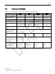
Antennas 6.6 Technical specifications 6.6 Table 6- 4 Technical specifications Technical specifications of the antennas ANT 1, ANT 3 , ANT 3S and ANT 8 ANT 1 ANT 3 ANT 3S ANT 8 140 mm 50 mm 5 mm 4 mm 75 x 75 x 20 mm (L x W x H) 50 x 28 x 10 mm (L x W x H) 50 x 28 x 10 mm (L x W x H) M8 x 1.
Antennas 6.6 Technical specifications Table 6- 5 Technical specifications of the antennas ANT 12, ANT 18 and ANT 30 ANT 12 ANT 18 ANT 30 16 mm 35 mm 55 mm M12 x 1.0 x 40 mm (Ø x thread x L) M18 x 1.0 x 55 mm (Ø x thread x L) M30 x 1.5 x 61 mm (Ø x thread x L) Max. write/read distance antenna ↔ transponder (Sg) Housing dimensions Color Pale turquoise Material Plastic Crastin Plug connection M8, 4-pin; (pins on antenna side) Degree of protection to EN 60529 IP67 (front) Shock-resistant acc.
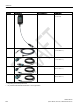
Antennas 6.7 Dimensional drawings 6.7 Dimensional drawings The cable length is 3 m. All dimensions are in mm.
Antennas 6.
Antennas 6.
Antennas 6.
RF300 transponder 7 Features of the RF300 transponders The RF300 transponders (RF3xxT) stand out particularly for their extremely fast data exchange with the RF300 readers (RF3xxR). With the exception of the RF320T transponder, all of the RF300 transponders have 8 to 64 KB of FRAM memory, which has an almost unlimited capacity for reading and writing.
RF300 transponder 7.1 Memory configuration of the RF300 transponders 7.1 1) Memory configuration of the RF300 transponders Physically identical memory When the OTP area is used, the corresponding user area (FF00-FF13) can no longer be modified (read only).
RF300 transponder 7.1 Memory configuration of the RF300 transponders EEPROM area The memory configuration of an RF300 transponder always comprises an EEPROM that has 20 bytes for user data (read/write) and a 4-byte unique serial number (UID, read only). For reasons of standardization, the UID is transferred as an 8 byte value through a read command to address FFF0 with a length of 8. The unused 4 high bytes are filled with zeros.
RF300 transponder 7.1 Memory configuration of the RF300 transponders Note Use of the OTP area is not reversible If you use the OPT area, you cannot undo it, because the OPT area can only be written to once.
RF300 transponder 7.2 SIMATIC RF320T 7.2 SIMATIC RF320T 7.2.1 Features RF320T 7.2.
RF300 transponder 7.2 SIMATIC RF320T 7.2.
RF300 transponder 7.2 SIMATIC RF320T Note Going below the distances If the distances (a and h) are not observed, a reduction of the field data results. It is possible to mount the MDS with metal screws (M3 countersunk head screws). This has no tangible impact on the range. 7.2.
RF300 transponder 7.2 SIMATIC RF320T 6GT2800-1CA00 Permitted ambient conditions Ambient temperature • During operation • -25 to +125 ℃ • During transportation and storage • -40 to +140 ℃ • IP67 • IPx9K Degree of protection to EN 60529 Shock-resistant to EN 60721-3-7, Class 7 M3 100 g 1) Vibration-resistant to EN 60721-3-7, Class 7 M3 20 g 1) Torsion and bending load Not permitted Design, dimensions and weight 7.2.
RF300 transponder 7.3 SIMATIC RF330T 7.3 SIMATIC RF330T 7.3.1 Features Table 7- 4 RF330T 7.3.2 Characteristics Area of application In production automation for identification of metallic workpiece holders, workpieces or containers.
RF300 transponder 7.3 SIMATIC RF330T 7.3.3 Mounting on/in metal Direct mounting of the RF330T on metal is permitted.
RF300 transponder 7.3 SIMATIC RF330T Figure 7-7 Mounting of the RF330T in metal without clearance Note Reduction of the write/read range Note that when the device is flush-mounted in metal without a surrounding clearance ≥ 10 mm, the write/read range is significantly reduced. 7.3.
RF300 transponder 7.
RF300 transponder 7.3 SIMATIC RF330T 7.3.
RF300 transponder 7.4 SIMATIC RF340T 7.4 SIMATIC RF340T 7.4.1 Features Table 7- 8 RF340T 7.4.
RF300 transponder 7.4 SIMATIC RF340T 7.4.3 Mounting on metal Direct mounting of the RF340T on metal is permitted. Mounting of RF340T on metal Figure 7-9 Mounting of RF340T on metal Flush-mounting of RF340T in metal: Figure 7-10 Flush-mounting of RF340T in metal The standard value for a is ≥ 20 mm. At lower values, the field data change significantly, resulting in a reduction in the range.
RF300 transponder 7.4 SIMATIC RF340T 7.4.
RF300 transponder 7.4 SIMATIC RF340T 6GT2800-4BB00 Design, dimensions and weight Dimensions (L x W x H) 48 x 25 x 15 mm Weight 25 g Type of mounting 2 x M3 screws ≤ 1.0 Nm 1) 7.4.5 The values for shock and vibration are maximum values and must not be applied continuously.
RF300 transponder 7.5 SIMATIC RF350T 7.5 SIMATIC RF350T 7.5.1 Features RF350T 7.5.2 Characteristics Area of application Identification tasks on small assembly lines in harsh industrial environments Memory size 32 KB FRAM user memory Write/read range See section Field data of RF300 transponders (Page 49) Mounting on metal Yes Degree of protection IP68 Ordering data Table 7- 11 Ordering data RF350T Article number 7.5.
RF300 transponder 7.5 SIMATIC RF350T Mounting of RF350T on metal Figure 7-12 Mounting of RF350T on metal Flush-mounting of RF350T in metal: Figure 7-13 RF350T flush-mounted in metal The standard value for a is ≥ 20 mm. At lower values, the field data change significantly, resulting in a reduction in the range.
RF300 transponder 7.5 SIMATIC RF350T 7.5.
RF300 transponder 7.5 SIMATIC RF350T 7.5.
RF300 transponder 7.5 SIMATIC RF350T 6GT2800-5BD00 Design, dimensions and weight Dimensions (L x W x H) 50 x 50 x 20 mm Weight 25 g Type of mounting 2 x M4 screws ≤ 1.5 Nm 1) 7.5.6 The values for shock and vibration are maximum values and must not be applied continuously.
RF300 transponder 7.6 SIMATIC RF360T 7.6 SIMATIC RF360T 7.6.1 Features RF360T 7.6.
RF300 transponder 7.6 SIMATIC RF360T Mounting of RF360T on metal Figure 7-17 Mounting of RF360T with spacer The standard value for h is ≥ 20 mm. Flush-mounting of RF360T in metal: Figure 7-18 Flush-mounting of RF360T with spacer The standard value for a is ≥ 20 mm. At lower values, the field data change significantly, resulting in a reduction in the range.
RF300 transponder 7.
RF300 transponder 7.6 SIMATIC RF360T 7.6.
RF300 transponder 7.6 SIMATIC RF360T 6GT2800-4AC00 6GT2800-5AC00 Design, dimensions and weight 7.6.5 Dimensions (L x W x H) 86 x 55 x 2.5 mm Weight 25 g Type of mounting • 2 x M3 screws ≤ 1.
RF300 transponder 7.7 SIMATIC RF370T 7.7 SIMATIC RF370T 7.7.1 Features The SIMATIC RF370T transponder is a passive (i.e. battery-free) data carrier in a square type of construction. RF370T 7.7.2 Characteristics Area of application Identification tasks on assembly lines in harsh industrial environments, due to high resistance to oils, lubricants and cleaning agents, and suitable for larger ranges, e.g.
RF300 transponder 7.7 SIMATIC RF370T 7.7.3 Mounting on metal Direct mounting of the RF370T on metal is permitted. Mounting of RF370T on metal Figure 7-21 Mounting of RF370T on metal Flush-mounting of RF370T in metal: Figure 7-22 RF370T flush-mounted in metal The standard value for a is ≥ 20 mm. At lower values, the field data change significantly, resulting in a reduction in the range.
RF300 transponder 7.7 SIMATIC RF370T 7.7.4 Mounting instructions It is essential that you observe the instructions in the Section Installation guidelines (Page 62). 7.7.5 Properties Description Type of installation Screw fixing (two M5 screws) Tightening torque < 1.
RF300 transponder 7.
RF300 transponder 7.8 SIMATIC RF380T Dimensions in mm 7.8 SIMATIC RF380T 7.8.1 Features The SIMATIC RF380T transponder is an extremely rugged and heat-resistant round data carrier suitable e.g. for applications in the automotive industry. SIMATIC RF380T transponder Characteristics Area of application Identification tasks in applications (e.g.
RF300 transponder 7.8 SIMATIC RF380T 7.8.3 Installation guidelines for RF380T It is essential that you observe the instructions in the Section Installation guidelines (Page 62). The following section only deals with features specific to the SIMATIC RF380T. 7.8.3.1 Mounting instructions Note Only use tag with original holder You are strongly recommended to only use the tag with the original holder specified.
RF300 transponder 7.8 SIMATIC RF380T Assembly of data memory with holder Figure 7-24 Assembly of tag with holder Scope of supply The holder is provided with all mounting parts and a mounting diagram. Mounting screws for securing the holder are not included. The mounting screws are of diameter M 10. The minimum length is 25 mm. The optional cover can be used for the long and short versions of the holder.
RF300 transponder 7.
RF300 transponder 7.8 SIMATIC RF380T 7.8.3.2 Metal-free area Direct mounting of the RF380T on metal is permitted. Mounting of RF380T on metal Figure 7-26 Mounting of RF380T on metal Flush-mounting of RF380T in metal: Figure 7-27 RF380T flush-mounted in metal The standard value for a is ≥ 40 mm. At lower values, the field data change significantly, resulting in a reduction in the range.
RF300 transponder 7.8 SIMATIC RF380T 7.8.4 Configuring instructions 7.8.4.1 Temperature dependence of the transmission window The guidelines in the section "Planning the RF300 system" apply to configuration of heatresistant data memories, with the exception of the limit distance and field length at temperatures above 85 °C. At temperatures above 85 °C, the length of the transmission window is reduced by up to 10%. 7.8.4.
RF300 transponder 7.8 SIMATIC RF380T The internal temperature of the tag follows an exponential function with which the internal temperature and the operability of the tag can be calculated in advance. This is particularly relevant to temperature-critical applications or those with a complex temperature profile. Ambient temperatures > 220°C Note Cancellation of warranty The data memory must not be exposed to ambient temperatures > 220 °C. No warranty claims will otherwise be accepted.
RF300 transponder 7.8 SIMATIC RF380T Figure 7-28 Graphic trend of temperature profile from above table The simulation results in the following: Following a simulation time of 36.5 hours, a total of 3 cycles were carried out, and an internal temperature of 90 degrees Celsius was reached.
RF300 transponder 7.8 SIMATIC RF380T 7.8.
RF300 transponder 7.8 SIMATIC RF380T WARNING Ignitions of gas-air mixtures • When using the RF380T transponder, check that the temperature class is kept to in conjunction with the requirements of the area of application. If the temperature ranges are exceeded during use of the transponder, gas-air mixtures may be ignited. • The maximum transmit power of the transmitter used to operate the transponder must not exceed 2 W. If the transmit power id not kept to, gas-air mixtures may ignite. 7.8.5.
RF300 transponder 7.
RF300 transponder 7.8 SIMATIC RF380T 7.8.
RF300 transponder 7.
ISO transponder 8 Features of the ISO transponders The transponders (MDS D) that are compatible with ISO 15693 represent a cost-effective alternative to RF300 transponders. The performance that can be achieved with this (transmission speed, memory size), however, is considerably less than with RF300 transponders. You will find more information on transmission speeds in the section "Communication between communications module, reader and transponder (Page 47)".
ISO transponder 8.1 Memory configuration of ISO the transponders 8.
ISO transponder 8.1 Memory configuration of ISO the transponders Memory areas Depending on the manufacturer of the transponder chip, the memory configuration of an ISO transponder consists of varying sizes of user memory. The typical sizes are 112 bytes, 256 bytes, 992 bytes EEPROM or 2000 bytes FRAM. Each ISO transponder chip has an 8-byte long unique serial number (UID, read only). This UID is transferred as an 8 byte value through a read command to address FFF0 with a length of 8.
ISO transponder 8.2 MDS D100 8.2 MDS D100 8.2.1 Characteristics MDS D100 Characteristics Area of application 8.2.2 From simple identification such as electronic barcode replacement/supplementation, through warehouse and distribution logistics, right up to product identification. Memory size 112 bytes of EEPROM user memory Write/read range See section Field data of ISO transponders (MDS D) (Page 52).
ISO transponder 8.
ISO transponder 8.2 MDS D100 Flush-mounting a ≥ 20 mm h ≥ 20 mm ① ② ③ Data memory Metal Non-metal Figure 8-3 Flush-mounting of MDS D100 in metal with spacer Note If the minimum guide values (h or a) are not observed, a reduction of the field data results. 8.2.
ISO transponder 8.
ISO transponder 8.2 MDS D100 8.2.
ISO transponder 8.3 MDS D117 8.3 MDS D117 8.3.1 Features MDS D117 8.3.2 Characteristics Area of application Very compact data carrier that can be cemented into objects where precise positioning is necessary; e.g. tool identification, workpiece holders etc.. Memory size 112 bytes of EEPROM user memory Write/read range See section "Field data of ISO transponders (MDS D) (Page 52).
ISO transponder 8.3 MDS D117 8.3.3 Mounting in metal Flush-mounted in metal ① Transponder ② Metal 8.3.
ISO transponder 8.
ISO transponder 8.4 MDS D124 8.4 MDS D124 8.4.1 Characteristics MDS D124 8.4.2 Characteristics Area of application Application areas in production automation (e.g. small paintshops up to +180 °C) Memory size 112 bytes of EEPROM user memory Write/read range See section "Field data of ISO transponders (MDS D) (Page 52)".
ISO transponder 8.4 MDS D124 8.4.
ISO transponder 8.4 MDS D124 Note Going below the distances If the distances (a and h) are not observed, a reduction of the field data results. It is possible to mount the MDS with metal screws (M3 countersunk head screws). This has no tangible impact on the range. 8.4.
ISO transponder 8.4 MDS D124 6GT2600-0AC10 • During transportation and storage Degree of protection to EN 60529 • at +180 ℃: Tested up to 5000 hours or 3000 cycles • -40 to +125 ℃ • IP68 2 hours, 2 bar, +20 °C • IPx9K steam jet: 150 mm; 10 to 15 l/min; 100 bar; 75 °C Shock-resistant to EN 60721-3-7 class 7M3 100 g 1) Vibration-resistant to EN 60721-3-7, class 7M3 20 g 1) Torsion and bending load Not permitted Design, dimensions and weight 8.4.5 Dimensions (Ø x H) 4 x 5.
ISO transponder 8.4 MDS D124 Identification II 1 G Ex ia IIC T3 to T6 Ga or II 1 D Ex ia IIIC T80 °C to T180 °C Da TÜV 12 ATEX 084413 X The temperature class or the maximum surface temperature depends on the maximum ambient temperature. The relationship between temperature class (gas) or maximum surface temperature (dust) can be found in the following table. Table 8- 9 Ambient temperature Ambient temperature range Temperature class Max. surface temperature -25 ... +150 ℃ T3 T180 -25 ...
ISO transponder 8.4 MDS D124 Note Installation and operating conditions for hazardous areas: • Use of the device in the vicinity of processes generating high charges is not allowed. • The device must be installed so that it is mechanically protected. • For applications requiring devices of category 1, the device must be mounted on a grounded, conductive base. • It must only be cleaned with a damp cloth. • The device is suitable for use in atmospheres containing dust, however not for full immersion in dust.
ISO transponder 8.5 MDS D126 8.5 MDS D126 8.5.1 Characteristics MDS D126 8.5.
ISO transponder 8.5 MDS D126 8.5.
ISO transponder 8.5 MDS D126 8.5.
ISO transponder 8.5 MDS D126 6GT2600-0AE00 Design, dimensions and weight 8.5.5 Dimensions (Ø x H) 50 x 3.6 mm Weight 13 g Type of mounting • 1 x M4 screw 2) ≤ 1 Nm • Glued 1) The values for shock and vibration are maximum values and must not be applied continuously. 2 ) To prevent it loosening during operation, secure the screw with screw locking varnish.
ISO transponder 8.6 MDS D127 8.6 MDS D127 8.6.1 Features MDS D127 8.6.2 Characteristics Area of application Very compact data carrier that can be screwed into areas where precise positioning is necessary; e.g. tool identification, workpiece holders etc.
ISO transponder 8.6 MDS D127 8.6.3 Mounting in metal Flush-mounted in metal ① Metal ② Transponders Note Damage to the transponder due to improper mounting To screw the MDS D127 into a suitable thread, use the supplied screw-in tool. This avoids damage to the MDS D127.
ISO transponder 8.6 MDS D127 8.6.
ISO transponder 8.6 MDS D127 6GT2600-0AF00 Design, dimensions and weight Dimensions (Ø x H) M6 x 5.8 mm Weight 1g Type of mounting • Glued • 1 x M3 screw 1) 8.6.5 The values for shock and vibration are maximum values and must not be applied continuously.
ISO transponder 8.7 MDS D139 8.7 MDS D139 8.7.
ISO transponder 8.7 MDS D139 8.7.2 Ordering data Table 8- 15 Ordering data for MDS D139 Article number MDS D139 Table 8- 16 6GT2600-0AA10 Ordering data for MDS D139 accessory Article number 8.7.3 Spacer 6GT2690-0AA00 Quick change holder (Ø x H): 22 x 60 mm 6GT2690-0AH00 Quick change holder (Ø x H): 22 x 47 mm 6GT2690-0AH10 Mounting on metal Direct mounting of the MDS D139/D339 on metal is not allowed. A distance of ≥ 30 mm is recommended.
ISO transponder 8.7 MDS D139 Flush-mounting It is possible to mount the MDS D139/D339 in metal. With large antennas, for example ANT D5, this leads to a reduction of ranges. h ≥ 30 mm a ≥ 100 mm Figure 8-15 Flush-mounting of the MDS D139/D339 in metal with spacer Note Going below the distances If the distances (a and h) are not observed, a reduction of the field data results. It is possible to mount the MDS with metal screws (M5). This has no tangible impact on the range.
ISO transponder 8.7 MDS D139 8.7.
ISO transponder 8.7 MDS D139 6GT2600-0AA10 Degree of protection to EN 60529 • IP68 2 hours, 2 bar, +20 °C • IPx9K steam jet: 150 mm; 10 to 15 l/min; 100 bar; 75 °C Shock-resistant to EN 60721-3-7 class 7M3 50 g 1) Vibration-resistant to EN 60721-3-7, class 7M3 20 g 1) Torsion and bending load Not permitted Design, dimensions and weight 8.7.6 Dimensions (Ø x H) 85 x 15 mm Weight 50 g Type of mounting 1 x M5 screw 2) 1.
ISO transponder 8.7 MDS D139 WARNING Gefahr durch elektrostatische Entladungen Potential electrostatic charging hazard Danger potentiel de charges électrostatiques Note Installations- und Betriebsbedingungen für den Ex-Schutzbereich: a) Der Einsatz des Gerätes in der Nähe von stark ladungserzeugenden Prozessen ist untersagt. b) Das Gerät ist mechanisch geschützt zu montieren. c) Die Montage muss auf einem geerdeten, leitenden Untergrund erfolgen. d) Die Reinigung darf nur mit feuchtem Tuch erfolgen.
ISO transponder 8.7 MDS D139 8.7.
ISO transponder 8.8 MDS D160 8.8 MDS D160 8.8.1 Characteristics MDS D160 Characteristics Area of application Thanks to its rugged packaging, the MDS D160 is a transponder that can be used under extreme environmental conditions. It is washable, heat-resistant and resistant to all chemicals generally used in the laundry process. Typical applications are, for example: 8.8.
ISO transponder 8.8 MDS D160 Table 8- 19 Ordering data for MDS D160 accessories Article number Spacer 8.8.4 6GT2690-0AG00 Mounting on metal Mounting on metal ① ② ③ Transponder h ≥ 10 mm Metal carrier Spacer Figure 8-17 Mounting the MDS D160 on metal with spacer Note Going below the minimum distance (h) If the minimum distance (h) is not observed, a reduction of the field data results. In critical applications, it is recommended that a test is performed.
ISO transponder 8.8 MDS D160 8.8.
ISO transponder 8.
ISO transponder 8.8 MDS D160 8.8.
ISO transponder 8.9 MDS D165 8.9 MDS D165 8.9.1 Features MDS D165 (special version) Characteristics Area of application The design of the transponder (self-adhesive label) permits a variety of designs, guaranteeing optimum dimensioning for the widest variety of applications. From simple identification such as electronic barcode replacement/supplementation, through warehouse and distribution logistics, right up to product identification. 8.9.
ISO transponder 8.9 MDS D165 8.9.
ISO transponder 8.9 MDS D165 6GT2600-1AB00-0AX0 Design, dimensions and weight 8.9.4 Dimensions (L x W x H) 86 x 54 x 0.
ISO transponder 8.10 MDS D200 8.10 MDS D200 8.10.1 Features MDS D200 8.10.2 Characteristics Area of application From simple identification such as electronic barcode replacement/supplementation, through warehouse and distribution logistics, right up to product identification. Memory size 256 bytes of EEPROM user memory Write/read range See section Field data of ISO transponders (MDS D) (Page 52).
ISO transponder 8.10 MDS D200 8.10.
ISO transponder 8.10 MDS D200 Flush-mounting a ≥ 20 mm h ≥ 20 mm ① ② ③ Data memory Metal Non-metal Figure 8-22 Flush-mounting of MDS D200 in metal with spacer Note If the minimum guide values (h) are not observed, a reduction of the field data results. 8.10.
ISO transponder 8.
ISO transponder 8.10 MDS D200 8.10.
ISO transponder 8.11 MDS D261 8.11 MDS D261 8.11.1 Features MDS D261 Characteristics Area of application The design of the transponder (self-adhesive label) permits a variety of designs, guaranteeing optimum dimensioning for the widest variety of applications. From simple identification such as electronic barcode replacement/supplementation, through warehouse and distribution logistics, right up to product identification. 8.11.
ISO transponder 8.11 MDS D261 8.11.
ISO transponder 8.11 MDS D261 6GT2600-1AA01-0AX0 Design, dimensions and weight 8.11.4 Dimensions (L x W x H) 55 x 55 x 0.
ISO transponder 8.12 MDS D324 8.12 MDS D324 8.12.1 Characteristics MDS D324 Characteristics Area of application Production and distribution logistics and product identification Can also be used in harsh environments under extreme environmental conditions (e.g. with higher temperature load). 8.12.2 Memory size 992 bytes of EEPROM user memory Write/read range See section "Field data of ISO transponders (MDS D) (Page 52).
ISO transponder 8.12 MDS D324 8.12.
ISO transponder 8.12 MDS D324 Note Going below the distances If the distances (a and h) are not observed, a reduction of the field data results. It is possible to mount the MDS with metal screws (M3 countersunk head screws). This has no tangible impact on the range. 8.12.
ISO transponder 8.12 MDS D324 6GT2600-3AC00 Degree of protection to EN 60529 • IP67 • IPx9K Shock-resistant to EN 60721-3-7 class 7M3 100 g 1) Vibration-resistant to EN 60721-3-7, class 7M3 20 g 1) Torsion and bending load Not permitted Design, dimensions and weight 8.12.5 Dimensions (Ø x H) 27 x 4 mm Weight 5g Type of mounting • 1 x M3 screw 2) ≤ 1 Nm • Glued 1) The values for shock and vibration are maximum values and must not be applied continuously.