Sierra Radio Systems Series 200 Control System Owners Manual Version 1.
Table of Contents Introduction Hardware overview Architecture Configuring and installing the hardware boards External connections Configuring the control system Introduction Using DTMF Using a PC and the CONFIG program Basic configuration parameters Radio port configuration Setting audio levels Using macros and creating custom commands Saving the configuration to a file Downloading configuration to the control system Terminology and file system Installing new firmware Control system operation Status indic
Introduction This manual provides all the basic information you need to know to get your control system installed, configured and on the air quickly. The control system is designed to work "out of the box" in a standard configuration. In most installations, all that is required is making the physical connections to power and the radio equipment and setting a few basic configuration parameters such as call sign and unlock code (password) and you are on the air.
Architecture Overview The Series 200 control systems are very modular and scalable. The basic architecture includes a master CPU board, from 1 to 8 Radio Control Boards (RCBs), and a backplane to provide the interconnection between boards.
System Installation Checklist Basic Checklist Summary This is a reminder of the basic steps to get your control system configured and running. Hardware installation and external connections Configure all necessary jumpers on each board. Plug boards into the backplane in the correct slots. Connect the control system to an external 12 VDC power source. Connect the CPU’s DB-9 connector to your PC.
Configuring the CPU Board Most of the boards in the control system have one or more jumpers that can be set to configure the board for various special purposes. The default configuration will be used in most cases. Refer to the SRS Hardware Reference manuals for more details on each board and the various jumper options. Here are the default jumper settings for the CPU and RCB boards. Basic Checklist Make sure all CPU board jumpers in properly set.
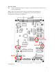
JU4 - PGC Pullup IN: Default. Install this jumper for using Con 3, the 10 pin header connector for incircuit programming. OUT: Remove the jumper when using Con 5, the ICD programming jack. NOTE: When using the ICD jack, you MUST cut the trace on the bottom of board.Default CPU Jumper Configuration JU1 DVB Default DIS JU3 OUT JU2 OUT JU4 IN All jumpers should be installed in the default positions indicated.
Configuring the Radio Control Board The radio control board provides the audio interface, level set, audio mixing, local telemetry (key up and CW ID) generation, serial radio control interface, extra user programmable open collector outputs. One RCB is required for every radio or VOIP computer in the system. Each RCB is configured to have one of several "personalities" including a repeater, RF link, remotely controlled base station, or VOIP computer.
JU5 - PL_Filter (NC) OUT: IN: Remove jumper is using a companion signaling board like the microwave or PL encode / decode boards. Default. Install the jumper when opearting the RCB without any signal conditioning boards. JU6 - DAC Pot Mid OUT: Default. Allows digital pots to be set by the local CPU. IN: Sets all four digital pots to mid scale. JU6 – Last Port Jumper (yes, there are two jumpers marked JU6) OUT: Default. Leave the jumper out for all RCB board except the last one.
Default RCB Jumper Configuration Radio Note: There are two jumpers labeled “JU6”, the “DAC pot mid” jumper and the “last port” jumper. The RCB jumpers should all be set to the defaults. Additionally, each RCB must be jumpered with the proper addresses set. Each RCB must be assigned one unique address from 0 to 7. Jumper block ____ must be set with a single jumper to properly route the Rx audio to the proper backplane bus signal.
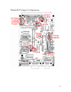
Hardware Orientation Power Supply Board The power supply board provides a power switch and a power LED. The power switch provides primary power to the CPU, RCB and accessory boards. The 12 VDC from the external power connector is routed to all boards in the card cage and is not switched. The power LED indicates that power is being supplied to the rest of the control system.
Configuring the Backplane The system will come configured as ordered. You will need to plug the various boards into the correct slots in the backplane. If your system is already assembled as desired, you can skip this section. The Power Supply, CPU and the first Radio Control Board (RCB) must be placed in specific slots. After the first RCB, all additional RCBs must be installed next to each other. There can be no gaps between the CPU and any of the RCBs.
A basic 8 port controller will have the following configuration… Typical 8 port controller Slot 0 1 2 3 4 5 6 7 8 9 10 11 12-18 Assignment Power supply Reserved for future expansion Reserved for future expansion CPU Radio control board - port 0 Radio control board - port 1 Radio control board - port 2 Radio control board - port 3 Radio control board - port 4 Radio control board - port 5 Radio control board - port 6 Radio control board - port 7 Empty Each port is assigned a "personality" which defines the
Using Optional Signaling Boards If optional signaling boards such as the microwave radio board or PL encode / decode boards are used, they are placed in the slot immediately to the right of the radio control board.
External Connections Backplane DC Power Connection Basic Checklist Make sure you connect the control system to an external 12 VDC power source. The control system typically uses +12 to +14 VDC and will operate down to10 VDC with no problems. The external DC power is supplied through a 2 pin connector mounted on the back of the control system. The alignment tab is on the top of the connector. As you look at the back of the backplane, the left pin is +12 VDC in and the right pin is ground.
CPU Board Connections The are three types of external connections on the CPU board, the configuration serial port connector, the general purpose I/O connector and the in-circuit programming connectors. Basic Checklist Make sure you connect the CPU’s DB-9 connector to your PC so you can use the CONFIG program to configure your control system. CPU Board Serial Port Connector This connection is a standard RS-232 ASCII interface between the control system and your computer.
Con_3 - In-Circuit Progamming Connector The in-circuit programming connector, Con_3, is used to download new versions of firmware to the main CPU. This is a 10 pin header connector designed to be used for incircuit programming with an ME Labs in-circuit programmer. General Purpose I/O Connector The GPIO connector provides 24 I/O signals that can be used for a variety of purposes.
Radio Control Board (RCB) Connections Basic Checklist Make sure you connect each radio, computer or other external device to the control system RCBs using the DB9 connector on the front of the RCB. DB-9 radio connections The control system has a female DB-9 connector which is used to connect to an external device including a repeater, link radio, remote base radio or computer system. The cable should have a male connector. This picture is the DB-9 connector as seen on the front of the control system.
Radio control cable. The radio control cable connects the control system to the individual radios. The cable is a 9 pin, shielded cable with all 9 connections wired straight through, with pin 1 to 1, 2 to 2, etc. In-circuit programming connector This is a 10 pin, dual row header connector. This connection is not used in normal operation. This is the connection where the in-circuit programmer in plugged in when downloading new versions of firmware to the RCB's local CPU.
Microwave Radio Interface Board 1 1 1 1 This board can be configured to drive a microwave radio that requires balanced audio and E & M signaling.
AS-3 Audio Squelch Board Pin 1 High impedence Rx audio input from receiver. Input can range from 0 to 2v peak-to-peak. Anything around 1 v p/p works great. Rx audio may be unsquelched. Pin 2 COR ("Carrier Operated Relay"), an active low signal. When the carrier is present, the COR pin must be pulled to ground. Pin 3 Ground Pin 4 PTT ("Push To Talk"), an active low signal. This is an open collector output that pulls to ground when the controller wants to key the transmitter.
Radio I/O – II (RIO-II) Board 22
Configuring the Control System 23
Control System Configuration Software Overview Sierra Radio Systems supplies a software configuration program called “config” that allows the system administrator to configure the control system through a Windowsbased PC. Config can be used in may different ways to configure a Sierra Radio Systems control system.
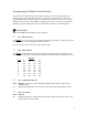
The steps are simple and in some cases some steps can even be skipped. Here is a description of what each step does… 1. Reset all parameters This will set all the configuration parameters in the config program to their normal default values. Then the configuration file “default.cfg” will be loaded. This is the starting point for your new controller configuration. 2. Customize basic parameters At a minimum, the controller should be personalized with its call sign, site prefix, location ID and unlock codes.
Call signs and location IDs can be up to 20 characters. The site prefix should be 1, 2 or three unique digits. All site prefix codes are # followed by the parameter that you enter. If you enter 123, then your prefix will be #123. Unlock codes should be something that only system administrators know. The minimum requirement is to specify unlock codes 1 and 2. 3. Configure Each Radio Port Each port is assigned a personality depending on the type of equipment and desired behavior.
Repeater port type Used for normal repeater operation. Loops repeater receiver audio to transmitter, uses transmitter carrier delay, mutes all DTMF audio to the transmitter but passes DTMF to the links, etc. Link port type Used for RF or “private” internet VOIP point to point network links. Does not loop audio, passes all DTMF tones, has no carrier delay unless the signal comes from a repeater input, etc. VOIP port type Used for IRLP, EchoLink and other “public” VOIP systems.
If the port type is “Remote Base” then the remote base type should be selected for the controller to generate the correct frequency and mode control data sent to the remote base radio. Groups The control system can support up to 3 independent groups of ports. The default is for all ports to operate together as group 0. Additional groups can be created by assigning group #1 or #2 to a port. Each group will act as if its members are the only radios in the system.
3. Set Audio Levels Each radio control board has 4 digitally controlled audio level set potentiometers. The control the receiver and transmitter audio levels, telemetry level generated by the RCB that is sent only to that specific transmitter and an auxiliary audio input level. The local telemetry generator per transmitter is used for dial tone, busy signal, function complete, CW ID and other functions.
pressing one of the buttons on the right side of the screen. It Up 10 and Down 10 lets you move quickly across the range of the pot while Up 1 / Down 1 let you fine tune your levels. 4. Set Command Names and Macros The control system comes with several dozen built in commands. In the simplest use mode, all you need to do is select your own personal unlock code and use all the generic built in commands and everything will work fine.
The dialog box will open with a default file name of “newfile”. It is recommended that you change the name to something more meaningful, like the name of the radio site or a version number of your own making. If you enter “bigmountain” for example, you will create a configuration file named bigmountain.cfg. To create your configuration file, just press the generate button and in a few seconds you are done.
Once the configuration has been downloaded into the controller, a notice box will appear to let you know that the configuration download is done. At this point you are done configuring your control system and have created a reusable configuration file.
Terminology and File System Files The standard distribution of config comes with a set of support files as follows… Config_xxx.exe This is the main config program. *.sll, *.dll, *.tkn These files are part of the config program. config.env The config program environment file containing PC installation and configuration data. default.cfg The default control system configuration file. scriptxx.scr Script files. These are empty and are modified by the user. My_reference.
All lines starting with a single quote ’ are comments and are ignored by the config program. Switches start with a forward slash / followed by a name such as port_0_type followed by a space then data. In this example the line assigns the port 1 personality type to be a 1 which means a repeater. Example: /port_1_type 1 Note that there are never any spaces inside the switch name. Also note there is always one, and only one space between the switch name and the data, in this case a “1”.
Script Files xxxxxx.scr The control system accepts commands either from the DTMF decoder or through the serial port on othe main CPU board. A simple program like HyperTerm can be connected to the serial port and you can simply type in commands and look at the results on your screen. Serial port settings are 9600 baud, N81. To make it more convenient to send several commands to the control system, you can create an ascii text file called a script file.
Script files support the following config.env environmental variables. When these script directives are encountered, they over ride the default values supplied in the config.env file. See the section on config.env for details. /command_delay 500 /digit_delay 20 Script files also support the following config file (xxxxxx.cfg) parameters. See the section on configuration file parameters for details.
Config Program Environment File config.env Various environment variables are stored in the config.env file. This file is set up once per installation and does not move with the specific controllers configuration. The format of the config.env file looks similar to the .cfg and .scr files but always contains a specific set of parameters. These parameters define which com port is used, the speed, and other useful or necessary installation specific information.
‘Comments Any line that starts with a single quote ‘ is a comment and the rest of the line is ignored by the config program. Any empty line is ignored by the config program. /serial_port yes Yes indicates that the serial port on the computer is active and when the config program is launched it should attempt to connect to the control system. No will prevent the config program from attempting to communicate with the control system through the serial port.
Installing New Firmware 39
Installing New Firmware To update the firmware on the main CPU or RCB boards, you must use an "in-circuit programmer". This device provides a connection between your computer and the control system boards. When installing new firmware, each board must be programmed individually. The only requirement is that the board must be powered and the in-circuit programmer must be connected. The in-circuit programmer we recommend is available from ME Labs and comes in many versions.
Option 3 - The Serial Programmer in a plastic case You must order the following… SRC The melabs Serial Programmer ICSP board only ACAD AC adapter 10CAB 10 pin header cable 9 pin serial cable If you only have a USB connection you can use a USB to serial adapter. We suggest you order the adapter from ME Labs because we know it will work. Order the "USB 1.1 to Serial Converter Cable" You can reach ME Labs on the web at www.melabs.
Connecting to the Control System The in-circuit programmer connects to the control system board with 4 signals including a clock, data, MCLR and ground. The connection at the programmer end is a 10 pin (2x5) header connector. The connection at the control system board end is either a 10 pin (2x5) pin header or a DB15 connector depending on which version of which board you are programming. This table shows which board support which kind of connector. 10 Pin Header DB-15 CPU v1.0 RCB pre-production RCB v1.
Connection method #1 – 10 pin header and ribbon cable. Use this with the CPU or RCB boards. Connection method #2 – 10 pin header to DB15 connector. Use with RCB boards.
Downloading New Firmware to the Boards Before you can install new firmware, you will need to install the ME Labs EPIC programmer software on your PC. This software is used to transfer the firmware image file from your PC to the flash memory of the CPU chips on the CPU, RCB or other boards. The software disk was included in the package when you got your EPIC programmer from ME Labs. You will also need the main CPU firmware or RCB firmware in the form of a .HEX file.
ME Labs EPIC In-Circuit Programmer Settings The programmer must be configured to program the correct type of processor, and set various other parameters. The EPIC software version should be v3.31 beta or later. Select the type of processor. For v1.
After opening the Radio Control Board firmware .
Downloading New Firmware to the CPU Board To download new firmware, you should follow these steps… 1 - Turn off the power to the control system. 2 – For the CPU board, plug the short 10 pin ribbon cable into the CPU board. For the RCB, you can either uses the 10 pin connector or the more convenient DB15 connector on the front of the radio control board PCB.
Control System Operation 48
Status indication LEDs on the Radio Control Board Power COR TX PL Dec DTMF Dec User 5 User 4 LED Functions Red power LED - Power has been applied to the RCB board.
Command Processor The heart of the control system includes a powerful command processor which reads all commands that come in either through the DTMF decoders or through the CPU board’s serial port, analyzes them and executes valid commands. Here are some important concepts to understand in the behavior of the command processor… 1. Command strings entered through the DTMF decoders or the serial port are inserted into the command processor and treated the same. 2.
Entering commands on a local repeater port When controlling from a repeater port, the controller prefix is a DTMF star “*”. For example when entering command 123 you would key up and enter “* 1 2 3”. After successful decoding and execution of the 123 command, the control system will generate the function complete “beep beep”. All DTMF digits are ignored until the “*” is entered. The controller can be configured to either pass all non-decoded DTMF or mute all non-decoded DTMF.
If you prefix the remote system, and another user is in the middle of controlling the system from another port, you will get a busy signal. The default is the telco “busy signal” (pulsing 440 Hz and 680 Hz). When the other user is done, you can then access the system. Entering commands on the local serial port on the main CPU board When controlling from the serial port, simply enter the string of command digits without any star “*”” or prefix “#xx” digits.
Control System Command Reference Guide 53
Control System Command Reference Guide The Series 200 control system comes with hundreds of built-in commands and command variations. Commands can be divided into 4 groups: common User Level commands, System Admin or “Super User” commands, System Configuration commands, and internal hardware commands. Each system operation will consider who is a “user” differently. In some systems, no user has access to any commands while in other systems, all users have some degree of command execution authority.
System Configuration Commands These commands are used by the system administrator to set up the specific behavior of the system. Typically these commands are defined once and don’t change. In most cases the default system configuration parameters supplied with the control system will be used unaltered by the system administrator.
System Normal Commands These commands return the control system to a known, safe state. Some normal commands reset parts of the control system and other commands can reset all control system states to a known condition. C300 (u) Site normal Sets normal conditions for the entire control system including all groups.
commands which require an unlock code. C304 (u) Link reset • Operates on the current group only • Connects link ports according to their normal link state as defined in the group definitions. • Does not change whether locals are connected. • Turns off remote monitor • Turns link delay on • Set link PL to normal state • Remote base transmitters disabled C305 (u) Local reset • Connects the normally connected local ports in the current group.
Identification C310 (u) Force CW ID Set ID timer to 0 on all radios in current group, thereby forcing ID on all transmitters. Default 1064 Hz tone. C311 (u) Force local CW ID Same as C310, but forces only all the local radios in the current group. C312 (u) Send CW ID Sends ID as telemetry. Currently goes only back to command source radio. This includes the primary local radio Default 800 Hz tone C313 (u) Send location ID in CW Returns the location string.
Repeater System on / off C002 (u) Repeater system off Disables all transmitters and command processing C003 (u) Repeater system on Inverse of C002 & only command recognized after C002 [] - command is always allowed. Repeater Port Commands C321 (u) Repeater on Enables repeat (loopback) on the local port from which the command comes, or the lowest logical radio in the same group as the source if it is a link, Connects the link if it was linked before.
C324 (u) Repeater status Provides on/off/disconnected status for local from which command comes, or lowest logical local in the same group as the command source if the source is a link.
Link Port Connection Commands C330 (u) Link off Unlinks specific radio in the current group. Syntax is *C330r, where r is the logical port number (linkmap is applied). This works with any port, including port 0, not just link ports. C331 (u) Link on Links specific radio to all other linked radios in group. Link is mapped to radio number by linkmap. [plre] - command is allowed from a link that is off if it is to turn on the same link. Syntax is *C331r, as for C330.
This applied only to the current group. Consider an example in which a group contains a repeater on port 0, and links on port 1, 2, and 3, and all are initially linked together. Issuing C33303D will link the repeater and port 3, and unlink both from ports 1 and 2. Ports 1 and 2 will remain linked together. The original state is returned by issuing C333D. The split link condition is only reset by C333D, the break all links command, C308, or by the global site normal, C300.
Port Access Mode – Carrier / CTCSS/DCS / Etc. C350 (u) COR mode COR only required for local repeater (command source port if it is a repeater, lowest logical numbered repeater port in the same group as the command source if the source is a link port). [pe] Command is not blocked if coming from a local even if PL is on and missing. C351 (u) PL mode PL required for local repeater (target port determined as for C350). C352 (u) Send PL status Uses status of first local in group.
Returns PL status for specific radio. Syntax is *C356r, where r is the port to change (link map is applied in versions after srsc0090e). [pe] Command is not blocked if coming from same port whose status it is requesting, even if PL is on and missing. C357 (u) Save PL mode for specific port Save the PL/COR mode for specific radio to eeprom. Syntax is C357r, when r is the port number (link map is applied).
Port Monitor Commands C340 (u) Remote monitors off Turns off remote monitor for the command source, with exception given above for remote monitor on. If the local port is in remmonl mode, then all remmonl ports in the group will have remmon cleared. If it is in remmon mode, remmon will be turned off for only that port. C341 (u) Remote monitors on Turns on remote monitor for the command source port, if that is a local (repeater).
Force Transmitter on / off C298 (u) Force transmitter on Keys up a specific transmitter. Syntax is *C298n, where n is the physical port number. This will timeout after 5 minutes, even if it is not reset with C299. C299 Cancel 298 Turns off force transmitter on. Syntax is *C299.
Loopback C250 (u) Turn on loopback Turns on loopback (repeats input to output) for a specific port in the current group. Useful for testing links. Syntax is *C250n, where n is a logical port number (linkmap applied). C251 Turn off loopback Turns off loopback globally - all groups. It does not affect the normal loopback for repeater ports. Delay C260 (u) Delay Does nothing but delays for a while. Syntax is *C260nnnD, which nnn is the delay in increments of 5 ms. The maximum value for nnn is 255 (1.
General Purpose I/O (GPIO) commands There are 5 user programmable general purpose output signals available on each radio control board (RCB). These signals are available on the DB15 aux I/O connector. Each signal is an open collector output with and active pull to ground. The output buffer can sink up to 500 ma and will pull to approximately 0.6v when active. When inactive, the signal will float. This works well to control external DC relays.
Remote Base Commands C380 (u) Enable remote base port transmit Enables remote base port transmit. Syntax is C380r, where r is the logical port number 0..7. Will not do anything unless the port link status is on. C381 (u) Disable remote base port transmit Disables remote base port transmit. Syntax is C381r, where r is the logical port number 0..7. C382 (u) Disconnect all remote base ports Disconnects all remote base ports (disables transmit and sets link on/off status to normal state).
C404 (u) Set remote base radio frequency in Hz Syntax is C404rffffffffff, where r is the logical port number and ffffffffff is the absolute frequency in Hz. The maximum value is 2^32 Hz, or a little over 4 GHz. For radios capable of higher frequencies, the frequency entered is interepreted as 10's of Hz.
C400 (u) Set remote base radio type This is considered a system administrator command because the remote base type is set once when the system is initially configured. Syntax is C400rnnnn r is the logical port number (0…7) nnn is the radio type C40A (u) Get remote base radio frequency C410 (u) Set remote base radio repeat mode normal Syntax is C410r, where r is the logical port number.
System Admin (Super User) Commands Test Tone Commands C219 (u) Turn on test tone Turns a 1 kHz tone on and off for test purposes. Syntax is C219r r is the physical port of the radio 0..8, where 8 is the CPU card C220 (u) Turn off test tone Turns off the test tone from C219 Syntax is C220r, as for C219. C221 (u) Set the test tone frequency Syntax is *C221ffffD, where ffff is the frequency in Hz. The value must be less than 4500 Hz. The default value is 1000 Hz, and is reset whenever the processor is reset.
nnn is the index of the sound sequence in the sound library. The tone amplitude is the same as that set for the test tone via command, C222. Link Port CTCSS/DCS Mode Commands C358 (u) Reset link PL mode to normal value Reset the PL mode for all non-local radios in the current group to the eeprom stored normal values.
Port Enable / Disable Master Commands C360 (u) Disable specific port Syntax is C360n, where n is the port number, with link map applied. This command does not save the state to eeprom, so will be reset to its previously saved state on a processor reset. Use C363 to save it permanently. This command is designed to be allowed only in unlock or super unlock mode and therefore will work on any radio, independent of the radio's group.
C365 (su) Enable a super disabled port Enable a super disabled radio. Syntax is as for C364. This command does not save the state to eeprom, so will be reset to its previously saved state on a processor reset. Use C367 to save it permanently. This command is designed to be allowed only in unlock or super unlock mode and therefore will work on any radio, independent of the radio's group. [pe] - command is not blocked if coming from the same radio it is commanding.
Command Enable / Disable Commands C368 (u) Command lockout specific radio Set command lockout for a radio. Syntax is C368n, where n is the port number, with link map applied. This command does not save the state to eeprom, so will be reset to its previously saved state on a processor reset. Use C36A to save it permanently. This command is designed to be allowed only in unlock or super unlock mode and therefore will work on any radio, independent of the radio's group.
DTMF Generation Commands C385 (u) Send dtmf string Sends dtmf string to a specific radio port. Syntax is C385rsssss…D r is the radio port 0..7 s is a dtmf string of up to 16 characters 0...
System Configuration Commands Unlock Code Management Commands C110 (su) Set unlock code Sets unlock code for enabling locked commands. This command requires a super unlock code (code #0 or #1). The unlock code number is returned in the telemetry if successful. No checking is done for conflicts with commands, so be careful that a command is not the same as the unlock code or is contained in the leading characters of the unlock code. The lowest index blank unlock code is set.
C114 Set unlock code 0 (no radio control cards) No unlock code is required, but all radio control cards must be removed from the controller first. Syntax is C114sssssD C115 (su0) Set unlock code 0 Sets unlock code 0. Requires unlock code 0 to be used to unlock the controller first.
Configuring Basic Parameters – ID, prefix, location ID Set the primary CW ID string Syntax is C116c1c1c2c2c3c3c4c4…D Each character in the string is defined by two DTMF digits. This table represents all CW characters. For example, W6ABC would be represented by… 91 60 21 22 23 W 6 A B C First Digit C116 (u) S116 (u) 0 1 2 3 4 5 6 7 8 9 0 0 1 2 3 4 5 6 7 8 9 1 space .
C117 (u) Get ID Returns the primary ID string C118 (u) S118 (u) Sets the secondary ID string. This is used by radios for which the secondary ID flag bit is set. C119 (u) Get ID2 Returns the secondary ID string Site Prefix Commands C120 (u) S120 (u) Sets the prefix string. Syntax is the same as for Set ID. Beware that only 0..9, A..D, and # can be used. The prefix can be up to 4 characters long. C121 (u) Get prefix Returns the prefix C122 (u) S122 (u) Sets the location string.
Macro programming commands C130 (u) S130 (u) Set macro Defines a macro. C130 is for dtmf input, S130 is for RS-232 input. Syntax is C130c1c2c2, where the syntax is as for set ID, except the first few characters must define the macro number, followed by a space. For S130, Syntax is S130nnn ssssssss C131 (u) Get macro Returns the macro string. Syntax is C131mD, where m is the macro number.
C136 Macro function complete telemetry If placed last in a macro, this command forces function complete telemetry at macro end. This is useful if a configuration command is implemented by the macro, and it is desirable for the telemetry to be function complete instead. This command does nothing outside of a macro. C137 Macro configuration complete telemetry If placed last in a macro, this command forces configuration complete telemetry at the macro end. This command does nothing outside of a macro.
CW Telemetry Commands C139 (u) Set CW WPM Sets the CW speed in words-per-minute for command telemetry.
Link Map C200 (u) Set link map The control system performs operations on port numbers 0…7. When we refer to these ports they are “logical ports” which are normally mapped onefor-one to the physical ports. This means that the RCB assigned a hardware port number of 0 will map to logical port number 0. With the link map you can assign any logical port to any physical port. In normal operation, all logical ports are mapped to their corresponding physical port.
Port Type Assignment Each port must be assigned a port type. A port type defines is a set of characteristics that make the port exhibit a specific behavior.
Examples *C2010D sets the first port (physical port 0) as the only repeater port *C202123456D set ports 2,3,4,5,6 as link ports *C2037D set port 7 to be a remote base port Any conflicts between these commands are resolved as the command is entered, in favor of values specified in the last command entered. The receive signal detect qualification and unqualification delays for each radio are set to the respective normal values for the radio type.
Group Configuration and Management The control system can support up to 4 independent groups. The default configuration uses one group (group #0) where all ports (0-7) are part of the same logical system. Ports can be grouped so that each logical group (#0 to #3) can operate independently. This means that ports in group 0 will not interact with ports in group 1, etc. The only limitation is that all groups must uses the same system settings.
Restore the configuration to the programmed group configuration. Used to undo C212. C214 (u) Set current group Explicitly set the current group. Syntax is C214n Where n is the new current group number C215 (u) Set current group, radio Explicitly set the current group to the one to which the specified port is a member. Syntax is C215n, where n is a port number. C216 (u) Reset current group Sets the current group to the normal value (group containing the command source).
Digital Pot Controls for Audio Level Setting The system contains multiple digital potentiometers used to set or “trim” various audio levels. There are two digital pots on the main CPU board and four digital pots on each of the radio control boards (RCB). Each pot can be set to a value between 0 and 255 where 0 is minimum, or no audio, 127 is midscale, and 255 is max audio. There are two ways to set the digital pots: setting a specific value and setting a value interactively.
3 and 9 increment and decrement the pot values by 10, respectively D saves the value * escapes and returns the value to what it was before entering this command 91
Setting Specific Digital Pot Values Setting audio levels to a specific value between 0 (minimum) and 255 (maximum) level.
Interactive Digital Pot Value Setting Interactively set the value of one pot. Syntax is *129rp…..D, where r is the radio (0..8, where 8 is the cpu card), p is the pot (0..3), and …. is a sequence of keystrokes to interactively set the pot value. Interactive "hot key" commands 1 and 7 increment and decrement the pot value by 1. 2 sets the pot value to 255, 5 sets the pot value to 127, 8 sets the pot value to 0, 3 and 9 increment and decrement the pot values by 10, respectively.
Port 5 Port 5 Port 5 Port 5 Port 5 Port 6 Port 6 Port 6 Port 6 Port 6 Port 7 Port 7 Port 7 Port 7 Port 7 Rx level Tx level Local telemetry External tone C224 C224 C224 C224 5 5 5 5 2 1 3 0 Rx level Tx level Local telemetry External tone C224 C224 C224 C224 6 6 6 6 2 1 3 0 Rx level Tx level Local telemetry External tone C224 C224 C224 C224 7 7 7 7 2 1 3 0 94
Command Telemetry Routing C225 (u) Command telemetry goes only to source. Responsiveness to RS232 serial port commands is much faster if CW telemetry is turned off while entering commands from the serial port. This command should normally be invoked before configuration via the serial port for that reason. C226 (u) Command telemetry goes to local (and source). This is the default.
Basic Configuration – ID, prefix, location ID S118 Set ID2 Sets the secondary ID string. This is used by radios for which the secondary ID flag bit is set. S120 Set prefix Sets the prefix string. Syntax is the same as for Set ID. Beware that only 0..9, A..D, and # can be used. The prefix can be up to 4 characters long. S122 Set location string Sets the location string. Syntax is the same as for Set ID. The location strings can be up to 9 characters long.
Internal Hardware System Commands C000 (u) Reset processor C001 Send firmware version Returns the CPU firmware code version C021 (u) Send RCB firmware version Returns the version string for one radio card. Syntax is C021r r is the physical port number. C004 (u) Reset reset counters Sets the reset counters to zero C005 Reset counter status Sends CW with reset count (# resets since *C004). Six values are returned. C006 (u) Exit safe mode This command is obsolete for software versions 0090 and later.
Firmware CRC Commands C010 (u) Boot CRC Returns CRC values determined at last configuration reset (first boot after programming CPU card processor, or first boot at eeprom valid byte reset, C100). The first value in the program ROM CRC, the second is the configuration parameter CRC in eeprom, the third is the macro table CRC in eeprom.
EEPROM Management Commands The system configuration is stored in a serial eeprom external to the main processor on the CPU board. The serial eeprom can store 3 copies of the configuration parameters, including the table of macros. They are designated the working set, backup set, and deep backup set. C100 (su) Force default configuration load on next processor reset. Sets serial eeprom valid byte to 0, invalidating the eeprom. New eeprom values will be loaded from the hard coded defaults on the next reset.
C104 (su) Deep configuration backup Copy backup configuration set to the deep backup set. This command should be used after the configuration backup command after a new configuration has been thoroughly tested. C105 (su) Deep configuration restore Copy deep backup configuration set to working set. Notice that this is NOT the inverse of the deep backup command which copies from the backup set to the deep backup set. This is changed from version of the program prior to 0094d.
C109 (u) Get eeprom word Returns one word from eeprom as decimal. Syntax is C109aaaaD Valid eeprom address is between 0 and 13823 C10A(su) Set eeprom bytes Writes multiple sequential bytes in the configuration eeprom. Syntax is C10A aaa Bnnn Bnnn Bnnn … D aaa eeprom starting address nnn byte values (in decimal) to be written to each byte This command has an 80 character limit to the sequence. Up to 16 bytes can be written at a time.
address range, they will be returned as 0. C10C (su) Get macro command table Copies macro command table to serial eeprom, starting at address 41505. Note: The number 12 is written to eeprom address 41504 to confirm that the macro table was copied. C10D (su) Set macro command table Writes macro command table from serial eeprom back to program memory (from where it is used). Checks for 12 in eeprom address 41504 before executing.
Configuration Parameters Timing Configuration Parameter Name dtmf_qual_delay telemetrydelayl xmittimeouts_long xmittimeouts_short dtmftimeouts busytimeouts id_idleto id_politeto id_absto id_lnkidleto cmdteldelays serteldelays dialtonetimeout parmtimeout fantimeouts rcvqdelays_loc rcvunqdelays_loc rcvqdelays_lnk rcvunqdelays_lnk rcvqdelays[] rcvunqdelays[] Description length of time dtmf tone must be detected by hardware to be recognized time from key up to start of key up telemetry time from key up to dr
Configuration Parameters Parameter Name Description CW Parameters cwfreqs cwamp cwwpm altidflags frequency for cw telemetry amplitude for cw telemetry cw speed for cw telemetry for each port, bit=1 for radio to send id_string2 (0) for each port, bit=1 for radio to append loc_string2 to id idlocflags (0) frequency for repeater and remote base ID (if enabled) idlocalfreq amplitude for repeater and remote base ID idlocalamp cw speed for ID to repeater and remote base idlocalwpm frequency for link ID idlinkf
Methodology for System-wide Audio Level Setting 105
Methodology for System-wide Audio Level Setting Buffered audio from each of up to 8 receivers is distributed on the backplane. Each radio control board selects from 0 to 8 of the receive signals to mix and send to that particular transmitter. Each receiver and transmitter level can be adjusted with internal digital potentiometers. The control system routes a standard internal signal level of 1v peak-to-peak for full system deviation from all receivers to all transmitters.
Using the config program or DTMF set the Port 0 receive level digital pot for 0.5v p/p. This will be the reference point for adjusting all other audio levels. Step 2 – Set the Port 0 Tx level. While still generating the signal used in step 1, set your service monitor to receive the signal now being transmitted by the radio on port 0. Set the port 0 transmit level pot so that the port 0 transmitter deviation is set to 2.5 Khz deviation. This will match the received signal to the transmitted signal.
Now, set the CPU board’s telemetry digital level set pot to 2.5 KHz deviation on the port 0 transmitter output. Step 7 – Turn off the built in test tone generator. *C220 Step 8 – Set local telemetry level on each transmitter. Now that the master telemetry bus is set, step through each RCB to set the telemetry level that is unique to each port. Set the receiving service monitor to the port 0 transmitter frequency.
Appendix 111
Glossary Radio Control Board One of the circuit boards plugged into the backplane, which provides the interface between the controller and a radio transmitter and receiver combination or any other audio signal source and destination, such as an IRLP node or telephone interface. Port Generic term for one full duplex connection to the controller. This could be a repeater, a link to another site, and IRLP node, or a remotely controller transceiver (remote base).
v0.90 software has limited support for this type of port. Unlock code and Superunlock code or password Many controller commands cannot be executed until an unlock code is entered. This prevents unauthorized users from reconfiguring the system. There are up to 20 unlock codes, which are designated unlock code number 0 to 19. There are two levels of unlock code, designated unlock code and superunlock code. Unlock codes 0 and 1 are super-unlock codes. The rest are just unlock codes.
Receive Qualification, Squelch and Transmit Timing In most cases, the audio from the receiver is muted when no carrier is detected. In this case, the receiver muting via the audio switches is not critical in the controller. It’s primary purpose is to avoid passing noise or other audio which opens receiver squelch when PL is not detected.
A weak signal may not provide a reliable PL signal. If PL is on, this can cause the audio switches to mute the weak audio. The receive unqualify delay should be set to prevent this from happening, while still providing the protection from passing grunge or undesirable keying of the transmitter. If the audio from the receiver is not squelched, a long squelch tail will be heard between the loss of carrier and the receiver unqualify delay timeout.
Telemetry Tones and Level Control The amplitude of individual telemetry tones and CW can be adjusted after the digital pots levels are properly set. There are no specific commands to make these changes. The parameters must be changed by directly modifying the parameter value where it is stored in the serial eeprom. As an example, lets change the amplitude of the CW ID for link ports. The default value is 40 in the range of 0 to 255.
Then reset the processor to load it into RAM.
Software Architecture and Theory of Operation This section of the manual is for those people interested in learning about the internal organization and behavior of the control system firmware. It is not necessary to understand all these details but will give you an deeper understanding of how it all works. All primary repeater control functions are executed by the processor on the CPU board.
Serial EEPROM Stored values of configuration parameters, stored values of unlock codes, stored and working table of macros. Memory usage for the Radio Control Board Program ROM Executable code and the library of sound sequences. digital pots settings, tone definitions and amplitudes, ID frequency, speed, and amplitude are downloaded from the CPU board when the system is reset.
2. Macro strings are stored in the serial eeprom. They are included in the backups. 3. A tone sequence library is stored in program ROM. Pointers to the tone sequence library for particular telemetry sequences are stored in RAM and serial eeprom. Initialization Default configuration parameter values are built into the CPU board program. The first time that the program is started after it is written to the processor chip ROM, it will load the default parameters into the serial EEPROM and into RAM.