INNOVA-SWITCH™ SERIES INSTRUCTION MANUAL Model 215 Mass Flow/Level Switch ( Model FS4200 Series – Mass Flow Switch / Model LS3200 Series – Point Level Switch ) Document IM 215 Rev-A.1 February 2006 Sierra Instruments, Inc., Headquarters 5 Harris Court, Building L Monterey, California, USA 93940 Toll Free: 800-866-0200 (USA only) Phone: 831-373-0200 ; Fax: 831-373-4402 Website: www.sierrainstruments.
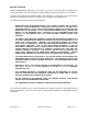
BEFORE STARTING SIERRA INSTRUMENTS appreciates your choosing our product for your liquid level or liquid/gas flow switching application. We are committed to providing reliable, quality instrumentation to our customers. To ensure the maximum and intended benefit of this instrument, we encourage you to read this brief operation and maintenance manual in its entirety prior to unpacking and installing the unit.
NOTICE This manual covers the following model numbers: Innova-Switch™ Series Models 215 - FS4200 215 - LS3200 Agency Approvals Explosion-Proof rating Mass Flow Switch FS42CN Point Level Switch LS32CN CENELEC European EEX d IIB T4 (Killark Enclosure) EEx d IIC T4 (Akron Electric Enclosure) See Figure 1A and 1B CSA Canadian Standards T4A Class I, Group B,C,D Class II, Group E, F, G (Both Akron Electric and Killark) FS42CS LS32CS Non-Approved Non-Explosion Proof FS42NX LS32NX (Ref.
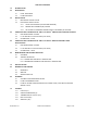
TABLE OF CONTENTS 1.0 INTRODUCTION 2.0 DESCRIPTION 3.0 4.0 5.0 2.1 LEVEL SWITCHING 2.2 FLOW SWITCHING INSTALLATION 3.1 MECHANICAL INSTALLATION 3.2 ELECTRICAL INSTALLATION 3.2.1 LOCAL ELECTRONICS (LE OPTION/STANDARD) 3.2.2 REMOTE ELECTRONICS (RE) OPTION 3.2.3 CE OPTION FILTER BOARD CONNECTOR PLATE WIRING (CE OPTION) OPERATION AND CALIBRATION OF THE Innova-Switch™ SWITCH FOR FLOW APPLICATIONS 4.1 PRE-OPERATIONAL CHECKS 4.2 L.E.D. AND RELAY STATUS LOGIC (FAIL-SAFE) 4.
1.0 INTRODUCTION ™ The SIERRA INSTRUMENTS Innova-Switch Switch is the state-of-the-art in gaseous and liquid flow switching or liquid level control. Flow or level detection is accomplished by using a high resolution thermal differential technique. The sensor wetted parts are of durable 316L series stainless steel, all welded construction with no moving parts. The switch is easy to install and adjust, giving reliable, low maintenance performance in the most demanding applications. 2.
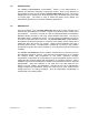
FIGURE 1A IM-215 Rev-A.1 LS3200/FS4200 Innova-Switch™ OUTLINE DIAGRAM STANDARD 2.
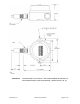
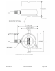
FIGURE 1B IM-215 Rev-A.1 LS3200/FS4200 Innova-Switch™ OUTLINE DIAGRAM STANDARD 2.
2.1 LEVEL SWITCHING The thermal differential created between the heated and reference unheated RTD pair is a function of the liquid or gas medium with which the sensor is in contact. The point level measurement application uses the heat transfer differences between two media to detect liquid level. For example, air has a relatively poor heat transfer characteristic so the heated sensor will become relatively hot.
FIGURE 2A: RELATIVE CHANGE IN RESPONSE OF A HEATED RTD IMMERSED IN VARIOUS MEDIA 2.2 Flow Switching Most mass flow monitoring techniques calculate mass indirectly by measuring volumetric flow such as gallons per minute or cubic cm per second, then either measure density separately or calculate it from temperature measurements of the fluid and, finally, combine density and volumetric flow to obtain mass flow.
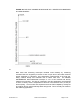
When the sensor is inserted into a liquid or gas the heated RTD is strongly affected by the velocity of the medium. Flow past the heated RTD changes the heat transferred from the surface of the sensor. This cooling effect reduces the temperature of the sensor. The Innova-Switch™ compares this change to a preset flow trip point to switch the output. Figure 2B shows the model FS4200 signal change vs. flow rate for air, light hydrocarbon liquids, and water.
FIGURE 2B Innova-Switch™ MODEL FS4200 FLOW RESPONSE FOR THREE MEDIA IM-215 Rev-A.
Figure 3.A shows a block diagram of the Innova-Switch™ switch. Once the switch is set to respond to the minimum and maximum flow rates (or wet vs. dry conditions), the trip point is set by adjusting the Trip Adjust Potentiometer. Solid state electronics transform the flow (or wetting) induced temperature differential into a voltage that is compared to a control voltage. Matching voltages cause actuation of a relay to indicate a change in state (flow vs. no-flow or dry vs. wet). FIGURE 3A: IM-215 Rev-A.
Figure 3B shows a block diagram of the Innova-Switch™ with the addition of an EMC filter required for the CE options (see section 7.0). FIGURE 3B: Innova-Switch™ MODELS WITH THE CE OPTION SWITCH BLOCK DIAGRAM IM-215 Rev-A.
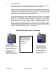
The instrument enclosure at the top of unit contains the Innova-Switch™ electronics board which is removable to access the terminal block and facilitate field wiring (see Figure 4.0). For applications where the electronics must be located away from the sensors due to elevated process temperature, accessibility, etc., another instrument head containing the electronics is remotely located (See option RE-Remote Electronics section 3.2.2). FIGURE 4 IM-215 Rev-A.
3.0 Installation 3.1 Mechanical Installation The standard Innova-Switch™ has a .75 inch (19.05mm) MNPT mount designed for easy installation through a threaded port. Optional configurations include .5” (12.7mm) or 1.0” (25.4mm) MNPT and flange mounts. Conduit is recommended for all wiring to the switch. *IMPORTANT* WHEN INSTALLING YOUR SIERRA INSTRUMENTS SWITCH INTO A PIPE OR VESSEL USE A 1 1/8 INCH (28.575mm) OPEN-END WRENCH TO TIGHTEN AT THE HEX FLATS OF THE MNPT OF A STANDARD SWITCH.
FIGURE 5: IM-215 Rev-A.1 PROPER ORIENTATION OF THE SENSOR PROBE FOR LEVEL AND FLOW APPLICATION IS INDICATED BY THE ARROW ON THE FLAT OF THE MOUNTING FITTING.
3.2 Electrical Installation 3.2.1 CE Option Filter Board Connector Plate Wiring (CE Option) Remove the instrument enclosure lid by unscrewing in a counter clockwise direction. Unscrew (CCW) the printed circuit board captive screws (See Figure 4.0 for locations). Remove the PC board by grasping the transformer and pulling it straight out. Connect power and alarm relay wiring to Terminal Block (TBB) as shown in Figures 6.0 and 6.0A.
mounting wings or bracket provided. Connect the switch wiring between the InnovaSwitch™ Switch remote electronics as shown in Figure 7.0. Connect power wiring and alarm relay wiring to the remote enclosure as shown in Figure 7.0. Upon completion of wiring reinstall the Innova-Switch™ electronics and secure with the captive screws. *IMPORTANT* BE SURE TO APPLY THE PROPER VOLTAGE AS CONFIGURED AT THE FACTORY. DO NOT APPLY 115 VAC TO 24 VDC VERSIONS OR 24 VDC TO 115 VAC VERSIONS (LIKEWISE 230 VAC).
IM-215 Rev-A.
IM-215 Rev-A.
3.2 Electrical Installation 3.2.3 CE Option Filter Board Connector Plate Wiring (CE Option) Remove the instrument enclosure lid by unscrewing in a counter clockwise direction. Unscrew (CCW) the printed circuit board captive screws (See Figure 4.0 for locations). Remove the PC board by grasping the transformer and pulling it straight out. Connect power and alarm relay wiring to Terminal Block (TBB) as shown in Figures 6.0 and 6A.
4.0 OPERATION AND CALIBRATION OF THE Innova-Switch™ FS4200 SWITCH FOR FLOW APPLICATIONS 4.1 Pre-Operational Check With the switch installed and process conditions at no-flow, the following procedure can be used to verify preliminary operation. 4.1.1 Remove the instrument enclosure cover by turning counter clockwise (ccw) to expose the Innova-Switch™ Switch electronics. 4.1.2 Turn on power at its source. 4.1.3 Observe that either the red or green LED comes on. 4.1.
FIGURE 8.0 4.2.3 Innova-Switch™ ELECTRONICS Alternate Operation (Field Selectable) The relay logic may be reversed by moving the J-2 jumper to position A(1-2). (Refer to Figure 8.0.) SENSOR STATUS RED LED GREEN RELAY LED COIL STATUS No Flow or Flow Below Set Point ON OFF RELAY CONTACT STATUS o NC Deactivated o NO o NC Flow or Flow Above Set Point OFF ON Activated o NO IM-215 Rev-A.
FIGURE 9.0 4.3 Innova-Switch™ FS4200 FLOW SWITCHCALIBRATION REFERENCE DRAWING Calibration – Flow **IMPORTANT** FOR OPTIMUM OPERATION, CALIBRATION MUST BE ACCOMPLISHED IM-215 Rev-A.
AT ACTUAL PROCESS TEMPERATURE AND PRESSURE CONDITIONS IN GASES AND AT ACTUAL PROCESS TEMPERATURE CONDITIONS IN LIQUIDS. See Figures 8.0 and 9.0 for location of potentiometers and LEDS on electronics PCB. 4.3.1 Calibration Procedure for Flow Switches 1. Remove the instrument enclosure lid by turning ccw. 2. Apply power to FS4200. Allow 5 minute warm-up. 3. Ensure that the pipeline is filled with fluid and at no or minimum flow. 4. Set the trip adjust pot to zero fully counterclockwise (fully ccw).
following procedure can be used to verify preliminary operation. 1. Remove the instrument enclosure cover by turning counter clockwise to expose the LS3200 Switch electronics. 2. Turn on power at its source. 3. Observe that either the red or green LED comes on. 4. If neither lamp illuminates refer to the trouble shooting Section, 6.2. 5.2 L.E.D. and Relay Status Logic (Fail-Safe) 5.2.1 The L.E.D.s (Red and Green) are an indication of the sensors status (ie.
Dispersion Fluid (ie. hydrocarbons) o NO o NC Wet, or Higher Thermal Dispersion Fluid OFF ON Activated o NO (ie. water) See Page 26 For Fuse Value FIGURE 8.0 5.3 Innova-Switch™ ELECTRONICS Calibration – Level **IMPORTANT** FOR OPTIMUM OPERATION CALIBRATION MUST BE ACCOMPLISHED AT ACTUAL PROCESS TEMPERATURE CONDITIONS. IM-215 Rev-A.
FIGURE 10.0 Innova-Switch™ LS3200 POINT LEVEL SWITCH CALIBRATION REFERENCE DRAWING 5.3 Calibration - Level Using Figure 10.0 as a location guide adjust the system as follows: 1. Remove the instrument enclosure lid by turning ccw. 2. Apply power to the unit. Allow 5 minute warm-up. 3. For optimum calibration results, wet sensor and drain but do not dry. 4. Ensure that the tank liquid level is below the probe sensor tips. IM-215 Rev-A.
5. Set the trip adjust pot to zero, fully counterclockwise (fully ccw). 6. Adjust the zero adjust pot so that the Red LED just does illuminate. This is a 25 turn pot. If the green LED is on, turn the pot counterclockwise (ccw). If red LED is on, turn the pot clockwise (cw). 7. Toggle the zero adjust pot back and forth until the switching point is well defined. Leave the Red LED illuminated. 8. Raise the level of the liquid to be detected until the probe/sensor tips are submerged and wet (covered).
6.0 INTENANCE AND TROUBLE SHOOTING 6.1 Cleaning The switch can be cleaned by soaking, spraying solvents or detergent-and-water onto the sensor tubes, or by ultrasonic cleaning. Lime deposits can be safely removed by soaking in 20% hydrochloric acid. Warming to 150°F is permissible to speed this process. The acid must be thoroughly rinsed off once cleaned.
6.2.2 Sensor/Electronics Functionality Verification 1. Turn power off to Innova-Switch™. 2. Allow a 5 minute cool down. 3. Measure the resistance of each RTD at pins 1 and 6 of TBA (see Figure 6.0 or 7.0) for the hot RTD and pins 3 and 5 of TBA for the cold RTD. These resistances should be 110 ± 10 ohms (with sensors at approximately 70°F) and within 5% of each other in value. 4. Measure the insulation resistance between pin 1 of TBA and the case of the Innova-Switch™.
7.0 SPECIFICATIONS TYPE: Thermal Differential-Dual RTD Sensors PROCESS CONNECTIONS: 0.75” (19.05mm) MNPT Standard, 0.5"(12.7mm), 1" (25.4mm) MNPT, and various flanges optional. INSERTION LENGTH: Two inch (50.8mm) Standard, (shorter 0.5 inch (12.7mm) and longer to 120 inch (3048mm) optional). CONSTRUCTION MATERIALS: Wetted parts are 316L SS welded construction (alternate materials for corrosive environments available as options. Consult factory.
8.0 WARRANTY AND SERVICE 8.1 Warranty SIERRA INSTRUMENTS Corporation warranties Innova-Switch™ switches for a period of two years from the date of shipment and will repair or replace this product in the event of a defect in materials or workmanship. To have a product repaired, it should be returned at customer's expense, after obtaining return authorization as described in Section 8.
8.4 Spare Parts List Part No. Description Innova-Switch Electronics 200203.1 FS42/LS32 – 110Vac 200203.2 FS42/LS32- 24Vdc 200203.3 FS42/LS32 - 220Vac 200203.5 FS42/LS32 w/ HS Relay (Specify Voltage) 200540.1 FS4100/LS3100 -110Vac 200540.2 FS4100/LS3100 - 24Vdc 200540.
9.1 VOLUME FLOW CONVERSION CHART Convert known units to cubic feet per second (CFPS) or gallons per minute (GPM) for use with Chart A.2 TO CONVERT FROM TO MULTIPLY BY Gallons Per Minute (GPM) Cubic Feet Per Per Second (CFPS) 2.228 E-03 Gallons Per Day (GPD) CFPS 1.547 E-06 Barrels Per Day (BPD) CFPS 6.531 E-5 Cubic Ft. Per Minute (CFPM) CFPS 1.667 E-02 Cubic In. Per Minute (CIPM) CFPS 9.645 E-06 Milliliters Per Minute (MLPM) CFPS 5.886 E-07 Milliliters Per Second (MLPS) CFPS 3.
9.2 IM-215 Rev-A.
9.3 FLOW OF WATER THROUGH SCHEDULE 40 STEEL PIPE IM-215 Rev-A.
10.0 10.1 IM-215 Rev-A.
10.2 IM-215 Rev-A.
10.3 IM-215 Rev-A.1 THERMOCOUPLE OUTPUT (TO) and 10.
IM-215 Rev-A.