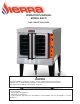
OPERATOR'S MANUAL MODEL SRCO GAS CONVECTION OVEN Improper installation, adjustment, alteration, service or maintenance can cause property damage, injury or death. Read the installation, operating and maintenance instructions thoroughly before installing or servicing this equipment. DANGER If you smell gas: Shut off gas to the appliance. Extinguish any open flame.
SAFETY PRECAUTIONS Before installing and operating this equipment, be sure everyone involved in its operation is fully trained and aware of precautions. Accidents and problems can be caused by failure to follow fundamental rules and precautions. The following symbols, found throughout this manual, alert you to potentially dangerous conditions to the operator, service personnel, or to the equipment. This symbol warns of immediate hazards which will result in severe injury or death.
TABLE OF CONTENTS Congratulations! You have purchased one of the finest pieces of heavy-duty commercial cooking equipment. You will find that your new equipment, like all Sierra equipment, has been designed and manufactured to meet the toughest standards in the industry. Each piece of Sierra equipment is carefully engineered and designs are verified through laboratory tests and field installations. With proper care and field maintenance, you will experience years of reliable, trouble-free operation.
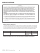
SPECIFICATIONS Local codes regarding installation vary greatly from one area to another. The National Fire Protection Association, Inc. states in its NFPA 96 latest edition that local codes are the “authority having jurisdiction” when it comes to installation requirements for equipment. Therefore, installations should comply with all local codes. Sierra reserves the right to change specifications and product design without notice.
GAS SUPPLY The serial plate indicates the type of gas the unit is equipped to burn. All Sierra equipment is adjusted at the factory. Check type of gas on serial plate. These models are design-certified for operation on natural or propane gases. For natural gas, the regulator is set to deliver a 4" W.C. pressure to the manifold. For propane gas, it is set to deliver 10" W.C.
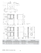
SIERRA SRCO Convection Oven 6
MINIMUM CLEARANCES There must be adequate clearance between the left side of the ovens and combustible construction. Adequate clearance must be provided in the aisle to allow the doors to open sufficiently to permit the removal of the racks and for serviceability. Although no clearance is required behind the motor on the rear of the oven, care must be taken to provide adequate air circulation to prevent the motor from overheating.
Installation These installation procedures must be followed by qualified personnel or warranty will be void. Local codes regarding installation vary greatly from one area to another. The National Fire Protection Association, Inc. states in its NFPA 96 latest edition that local codes are the “authority having jurisdiction” when it comes to installation requirements for equipment. Therefore, installations should comply with all local codes.
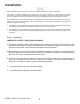
Step 2: Installation of Legs on Single-Deck Ovens (For Stacking kit, refer to instructions included with kit) 1. Raise oven sufficiently to allow clearance for the legs to be attached. Use of a lift truck or other mechanical lifting means is recommended. For safety, “shore up” and support the oven with an adequate blocking arrangement strong enough to support the load. (If it is absolutely necessary to rest the oven on its side, rest it on its left side.) 2.
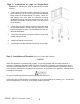
Step 4: Connect Electricity ELECTRIC GROUNDING INSTRUCTIONS This appliance (120V ovens only) is equipped with a three-prong (grounding) plug for your protection against shock hazard and should be plugged directly into a properly grounded three-prong receptacle. Do not cut or remove the grounding prong from this plug.
These models are design-certified for operation on natural or propane gases. For natural gas, the regulator is set to deliver a 3.5" W.C. pressure to the manifold. For propane gas, it is set to deliver 11" W.C. This appliance should be connected ONLY to the type of gas for which it is equipped. The inlet pressure before the regulator should be 6-10" W.C. for natural gas or 11-14" W.C. for LP gas. An adequate gas supply is imperative.
Control Panel Fan Speed Use to select fan speed (HI or LOW). The appropriate speed is determined by the type of food being cooked. Fan Mode In COOK mode, the fan runs continuously except when the doors are open. The fan does NOT cycle with the operation of the burners. Cook Timer Turn knob to set a time duration. An alarm will sound when the timer runs out. The timer is a reminder to the user; The timer does not control the oven In COOL mode, the fan runs continuously even if the doors are open.
OPERATION EXPLOSION HAZARD In the event a gas odour is detected, shut down equipment at the main shut off valve. Immediately call the emergency phone number of your gas supplier. To eliminate gas build up which could result in an explosion, in the event of main burner ignition failure a five minute purge period must be observed prior to re-establishing ignition source. No attempt should be made to operate oven during a power failure.
To cook, do the following: 1. Turn the oven ON using the Power Switch at the bottom of the control panel. 2. Select the desired fan speed using the Fan Speed switch. The appropriate fan speed (HI or LOW) depends on the type of food being cooked. 3. Switch the Fan Mode switch to COOK. The fan will run continuously when the oven doors are closed (the fan does not cycle on and off with the burners).
is a starting point. The actual best cooking time and temperature will depend on such factors as size of load and mixture of recipe (particularly moisture). Once an appropriate time and temperature has been established for a particular product and load, you will find the result of succeeding loads to be similar. OVERLOADING Do NOT overload the oven. The size of the load that can be cooked satisfactorily depends largely on the particular product.
COOKING PROBLEMS AND SOLUTIONS If… then… Cakes are dark on the sides and not done in the center… lower oven temperature. Cake edges are too brown… reduce number of pans or lower oven temperature. Cakes have a light outer color… raise temperature. Cakes settle slightly in the center… bake longer or raise oven temperature slightly. Do not open doors except to load or unload product. Cakes ripple… do not overload pans or use batter that is too thin. Cakes are too coarse… lower oven temperature.
Baked Goods Bread, 2 lb. loaf 35 min. 375°F 3 5-10 min. 400°F 5 Cornbread 18 min. 400°F 5 French Bread 10 min. 375°F 5 Sheet Cake 18-20 min. 300°F 5 Cream Puffs 20 min. 375°F 5 6 min. 400°F 5 18 min. 300°F 5 Yeast Rolls, sheet pan 16-18 min. 325°F 5 Pineapple Upside Down Cake 25-30 min. 325°F 5 Apple Turnovers 15-18 min. 350°F 5 Fruit Cobbler 22-25 min. 375°F 5 Brownies 15 min. 350°F 5 Danish Pastry 12 min. 325°F 5 Pie Shells 12 min.
CLEANING Sierra equipment is sturdily constructed of the best materials and is designed to provide durable service when treated with ordinary care. To expect the best performance, your equipment must be maintained in good condition and cleaned daily. Naturally, the periods for this care and cleaning depend on the amount and degree of usage. Following daily and periodic maintenance procedures will enhance long life for your equipment.
SEMI-ANNUAL CLEANING At least twice a year have your Sierra Authorized Service Agency or another qualified service technician clean and adjust the unit for maximum performance. At least twice a year the oven’s venting system should be examined and cleaned. CLEANING STAINLESS STEEL SURFACES To remove normal dirt, grease and product residue from stainless steel that operates at LOW temperature, use ordinary soap and water (with or without detergent) applied with a sponge or cloth.
ADJUSTMENTS ADJUSTMENTS AND SERVICE WORK MAY BE PERFORMED ONLY BY A QUALIFIED TECHNICIAN WHO IS EXPERIENCED IN, AND KNOWLEDGEABLE WITH, THE OPERATION OF COMMERCIAL COOKING EQUIPMENT. HOWEVER, TO ASSURE YOUR CONFIDENCE, CONTACT YOUR AUTHORIZED SERVICE AGENCY FOR RELIABLE SERVICE, DEPENDABLE ADVICE OR OTHER ASSISTANCE, AND FOR GENUINE FACTORY PARTS.
ADJUSTING DOOR SWITCH The door switch detects when the oven doors are open. As adjusted at the factory, when the doors are opened more than 2 to 4 inches, the burners and fan should shut off (unless the fan is switched to “COOL” mode). To adjust the door switch, do the following: 1. Remove lower front panel that covers the door chain mechanism. 2. Close both doors. 3. Check that the door switch cam is operating the door switch.
TROUBLESHOOTING ADJUSTMENTS AND SERVICE WORK MAY BE PERFORMED ONLY BY A QUALIFIED TECHNICIAN WHO IS EXPERIENCED IN, AND KNOWLEDGEABLE WITH, THE OPERATION OF COMMERCIAL COOKING EQUIPMENT. HOWEVER, TO ASSURE YOUR CONFIDENCE, CONTACT MVP GROUP FOR RELIABLE SERVICE, DEPENDABLE ADVICE OR OTHER ASSISTANCE, AND FOR GENUINE FACTORY PARTS.
SIERRA SRCO Convection Oven 23
SIERRA SRCO Convection Oven 24
CONTROL PANEL ACCESS To access the control panel components, remove the screw at the top of the control panel and pull the top of the control panel out and down (see drawing below). A wiring diagram for the oven is located on the side of the control panel assembly. Accessing Control Panel Components CLEANING OF AIR INTAKE GRATING AND BLOWER FAN WHEEL To clean the air intake grating or blower wheel, do the following: 1.Remove racks and rack guides. 2.Clean intake wire grating with wet rag.
Electrical Schematic for 120 Volt SIERRA SRCO Convection Oven 26
PARTS SIERRA SRCO Convection Oven 27
SIERRA SRCO Convection Oven 28
SIERRA SRCO Convection Oven 29
Pic # 1 2 3 4 5 6 7 8 9 10 11 12 13 14 15 16 17 18 19 20 21 22 23 24 25 26 27 28 29 30 31 32 33 34 35 36 37 38 39 40 41 42 43 Part Number FS-COP0001 FS-COP0002 FS-COP0003 FS-COP0004 FS-COP0005 FS-COP0006 FS-COP0007 FS-COP0008 FS-COP0009 FS-COP0010 FS-COP0011 FS-COP0012 FS-COP0013 FS-COP0014 FS-COP0015 FS-COP0016 FS-COP0017 FS-COP0018 FS-COP0019 FS-COP0020 FS-COP0021 FS-COP0022 FS-COP0023 FS-COP0024 FS-COP0025 FS-COP0026 FS-COP0027 FS-COP0028 FS-COP0029 FS-COP0030 FS-COP0031 FS-COP0032 FS-COP0033 FS-COP0034
Natural to LP gas conversion Procedure This work needs to be done by a certified service technician. Proper safety precautions need to be done. Unplug oven from power and disconnect from gas line. Remove lower front burner cover. Open doors and remove screws on top to remove cover Open the control panel. To do this, reach under top and loosen control panel knob, then swing panel forward.
Remove side panel of oven next to control panel by removing screws on bottom and rear of oven to expose the gas system and electrical system. This below, is what you will see. The burner orifices and the regulator need to be changed. The gas type information needs to be changed as well. The burners need to be removed. The burner manifold needs to be disconnected. On front of oven, use wrenches to loosen gas line connection to burner manifold.
Pull manifold assembly off gas supply tube remove from oven. Using wrench, remove existing gas orifices for Natural Gas, and replace with new LP Gas orifices supplied in conversion kit. Use Loctite 542 thread sealer or equivalent to seal and lock new orifice threads.
On side of oven, locate gas control valve. Locate regulator screw cover on top. (Scrape out soft silicone filling screw driver slot.) Use screwdriver to remove cover. See photo below: After cover is removed, use a small screwdriver to carefully turn counterclockwise, the plastic spring retainer ring shown below. Keep turning until ring comes out and existing spring is exposed. Remove the spring.
Locate the new regulator kit. Carefully remove the new spring in this bag, and place it where the old one was removed. Place the new spring retainer cap on top of the spring and carefully turn it clockwise to begin tightening the spring. Using a fine screwdriver, carefully tighten the retainer ring down until it is 0.20” (slightly less than 1/4” from the top surface of the spring assembly. This will set the regulator to the 11” W.C. needed to run the burners on LP gas.
Turn on oven. Oven should light normally and operate normally if new regular spring and spring retaining cap were installed properly. Screw retaining cap down clockwise to increase pressure to manifold, turn counterclockwise to reduce pressure. When manifold is 11” W.C. as shown, flames and combustion will be optimized and you will see a good blue flame. Turn off oven. Remove oven from gas supply. Remove gas gage from burner manifold and replace with original brass pipe plug.
5659 Royalmount Ave Montreal, QC, Canada H4P 2P9 12000 Biscayne Blvd, Suite #108 Miami, FL, United States 33181 (514) 737-9701 (888) 275-4538 (786) 600-4687 (844) 218-8477 www.mvpgroupcorp.com 2017-04 A product with the Sierra name incorporates the best in durability and low maintenance. We all recognize, however, that replacement parts and occasional professional service may be necessary to extend the useful life of this unit.
WARRANTY INFORMATION FORM Fill in the blanks and keep this paper with the original invoice in a safe place for future service purpose. 1.Date of purchase :____________________________________ 2. Model No. : ____________________________________ 3. Serial No.