
Indoor Fireplace User Manual


G8860 _4 Installation Manual NZ
5
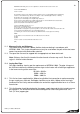
C
A
B
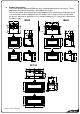
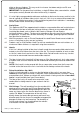
2.0 Creating the Cavity:
The dimensioned drawing below shows the size of the opening that must be created to keep
combustible materials at the required distance from the heater.
Note: It is not necessary to line the side, top or back of the cavity.
2.1 Where possible, it is recommended that cavity is made slightly larger than the above
dimensions to give the installer the maximum amount of space to work in.
2.2 The IB1100 and IB850 have their electronics compartment protruding from the left hand side
of the fire and the resulting offset needs to be taken into account when installing into a tight
masonry cavity.
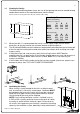
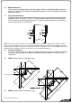
2.3 If fitting the heater into a non-masonry wall, the first thing installers MUST do after
unpacking the fire is to bend and re-fix the triangle shaped spacers on each side and rear of
the heater. The picture below shows how this is done. Note: This is not necessary for
masonry installation.
2.4 If the fire does not fit into the timber cavity that has been created, (after these spacers have
been put in place), then THE CAVITY MUST BE ENLARGED.
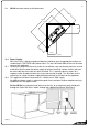
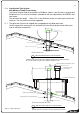
3.0 Ventilating the Cavity
When a cavity is being created for the fire in a timber framed
wall, ensure that it is not a fully sealed space. Ventilation MUST
be provided at the base of the cavity and, if possible, leave the
top of the cavity open into the ceiling space otherwise another
vent at the top of the cavity will be required.
NOTE: If an in-ceiling ventilation system is installed (such as
a DVS or HRV system), particular care must be taken to isolate
the cavity air space from the ceiling air space. Failure to do so
will result in the negative air pressure that is created in the ceiling
space, by the ventilation system, potentially having a detrimental
Ideal Cavity Dimensions:
(Timber framed walls)
All dimensions in millimetres
A B C
IB600 700 585 565
IB850 965 560 565
IB1100 1265 560 565
(Masonry Cavity)
A B C
IB600 600 570 520
IB850 950 545 520
IB1100 1265 565 565
(Check offset. Refer 2.2)