
Indoor Fireplace User Manual

G8860 _4 Installation Manual NZ
8
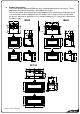
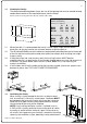
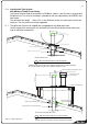
1260mm
2380mm
1190mm
560mm
596mm
596m
m
1683mm
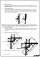
9.3 IB1100 minimum corner install dimensions:
10.0 Power Supply:
Whilst the cavity is being created consideration should be given to appropriate location of a
standard 3 pin, EARTHED 240V power outlet. This must be within 0.5m of the rear left hand
corner of the appliance.
10.1 Locating this plug within the cavity makes the installation very neat but the provision must be
made to be able to switch the power supply off and on (electrical isolation switch) and must
be accessible after the heater has been installed. This is normally done by means of a
separate switch located outside of the cavity and wired to the plug. This will allow service
technicians to isolate the power supply before performing service work on the appliance.
10.2 This appliance will draw a maximum of 1.2 Amps from a 240V supply.
No additional power supply is required for power flue installations and no telephone wiring is
needed for the i-con phone switch
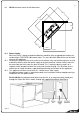
For the IB1100, the electrical cord (either from the fire, or an extension cord) should pass
through the Outer Skin Kit as shown, through the supplied Cord Strain Relief Bush.