
Matrix Routing System Operator's Manual


3
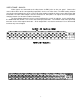
VIDEO FRAME - ANALOG
Video signals are connected to the video frame via BNC jacks on the rear panel. Connect the
source video cables to the corresponding input BNCs on the rear of the frame. The MRX routing switcher
must be the terminating device in the system. All video modules provide the video source with proper 75Ω
termination. All active video outputs must be terminated in 75Ω. (BNC’s for outputs that are beyond the
configured matrix size do not need to be terminated.)
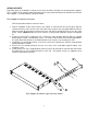
The figure below shows the rear of a system configured as a 32 X 32 switcher. In this configuration,
the bottom two rows of BNC’s are used as the video input connectors. The 32 BNC’s that make up the top
two rows are the video output connectors. All 32 output BNC’s need to be terminated. Use a 75Ω load to
terminate any unused output.