
User manual


16
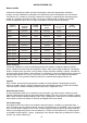
Diagrams of power supply connection
Das Gitter muss Verhältnis zum Ablüfter senkrecht aufgezetzt werden.
“0”
Phase
220-240 V ( 12 V *)
S
“0”
Phase
220-240 V ( 12 V *)
L
LT
N
“0”
Phase
220-240 V ( 12 V *)
N
LT
L
S
N
“0”
Phase
220-240 V ( 12 V *)
Power supply feed circuit
for fans with built-in switch
Diagram of connection of fan
without built-in switch to circuit,
where S is switch installed additionally.
Diagram of connection of fan
equipped with timer /timer
with humidity relay and built-in switch.
Diagram of connection of fan
equipped with timer /timer with
humidity relay and without built-in switch.
picture 1
picture 2
picture 3
picture 4
Diagrams in the pic.1, 3 ensure operation of fans, equipped with built-in
switch.
Diagrams in the show connection of fans without built-in switch.
Outer switch S is shown.
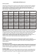
Fan switch off delay time is adjustable within the range of approx. 2 to 30
minutes.
Time can be regulated by potentiometer T. Delay increase direction is
clockwise, and delay decrease is anticlockwise).
Fans supplied with timer and humidity relay are turning onby certain humidity
level. (50-90%) and are regulated by potentiometer H by rotaiton clockwise to
increase and anticlockwise to decrease level during the time, adjusted
by timer.
Fans with timer and movement sensor switch on ventilator when a person
moves at a distance from 1 to 4 meters with viewing angle of the sensor of
o
100 across and automatically switch off the ventilator in time, set by the timer
from 2 to 30 minutes (by turning the T regulator clockwise for increase and
counterclockwise for decrease of the delay time).
Attention! Diagram of timer is situated under circuit potential.
It is forbidden to regulate timer's delay time unless fan is switched off the
mains.Diagram in shows connectionof lighting lamp to fan's timer
controlled by single switch (S is an outer switch).
When lightning lamp is off, fan works during the time, adjusted by timer.
pic.2, 4
pic.4
* - only for 12 V fans (as mentioned on the fan and the box)