
Manual

SK-5280 Status Display Module Installation Instructions
2 151238 Rev C
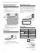
Mounting the SK-5280 into the
SK-2190 Accessory Cabinet
Follow these steps to properly mount the SK-5280 into the
SK-2190 cabinet:
1. Mount the remote cabinet using the cabinet mounting holes.
See Figure 4.
2. Remove power from the control panel.
3. Mount the SK-5280 onto the standoffs and bracket located
in the cabinet. See Figure 4.
Figure 4: Model SK-5280 Remote Installation
4. Connect the SK-5280 to the SK-5208 control panel as
shown in Figure 2.
5. Set the ID number. See the 5208 Installation Manual (PN
151204) for information on setting ID numbers.
6. Reconnect power to the control panel.
Wiring Relays
The four on-board relays can be triggered by the active low
outputs. For example, the alarm outputs can all be wired to relay
3 and the trouble relays can be wired to relay 4 (see Figure 5).
Figure 5: Relay Wiring on the SK-5280
Note: Figure 5 uses A7 and T7 to activate relays 3 and 4 as an
example. However, any of the outputs can be used to trip
any of the relays.
Wiring LEDs to Outputs
The outputs (A1-A10 and T1-T10) can be used to operate LEDs
used in a remote annunciator (see Figure 6). Outputs A1-A10 are
alarm outputs for the zones corresponding to those outputs. For
example, if the 5280 is programmed to output for zones 11-20,
then outputs A1-A10 will correspond with zones 11 through 20.
Outputs T1-T10 are trouble outputs for the zones corresponding
to those outputs. for example, if the 5280 is programmed to
output for zones 21-30, then outputs T1-T10 will correspond
with zones 21-30.
Figure 6: LED Wiring on the SK-5280
Specifications
Mounting
Holes
Programmable
Relays
Parameter Rating
Operating Voltage: 27.4 VDC max.
Current Draw: Standby: 10 mA
Alarm: 80 mA
Operating Temp: 32° to 120° F
(0° to 49° C)
Relay Rating: 2.5 A @ 30VDC/120VAC
Outputs: 100 mA each, 700 mA
max.
2 kΩ
Graphic Annunciator