SX-560 Embedded Intelligent Module Developer’s Reference Guide
© 2008 Silex Technology America, Inc.. All rights reserved. October, 2008 Silex Technology America SPECIFICALLY DISCLAIMS THE IMPLIED WARRANTIES OF MERCHANTABILITY AND FITNESS OF THIS PRODUCT FOR A PARTICULAR PURPOSE. Silex shall not be liable for any errors contained in this manual or for any damages resulting from loss of use, data, profits, or any incidental or consequential damages arising from the use of SILEX products or services.
Contents About This Reference Guide............................................................................................................................................ 1 Safety Precautions........................................................................................................................................................ 1 Emissions Disclaimer.............................................................................................................................................
SNMP Traps, Email Alerts, and GPIO Status ........................................................................................................... 36 Chapter 5 Interfacing the SX-560 to the OEM Device ................................................................................................. 37 SX-560 Power Requirements .................................................................................................................................... 41 Installing the SX-560........................
Figures Figure 1 SX-560 top and bottom view ............................................................................................................................ 3 Figure 2 Installing SX-560 Module in Evaluation Daughtercard................................................................................... 5 Figure 3 SX-560 Module Inserted in Daughtercard....................................................................................................... 8 Figure 4 Serial Port DB-9 Connector ......
Table 36 Table 37 Table 38 Table 39 Table 40 Table 41 Table 42 Table 43 Table 44 Page iv Server Information Commands ..................................................................................................................... 79 Service Commands ....................................................................................................................................... 81 SNMP Commands ......................................................................................................
About This Reference Guide This reference guide provides detailed specifications, diagrams and additional information required to integrate the SX-560 embedded intelligent module in a product. The intended audiences are the developers and engineers responsible for the integration of the module in another product. Safety Precautions ! To prevent damage to the SX-560 module’s electronic circuit components, follow established ESD practices and procedures for handling static-sensitive devices.
Page 2 Silex Part Number 140-00192-100 About This Reference Guide
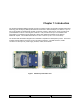
Chapter 1: Introduction The SX-560 embedded intelligent module provides a complete solution for integrating wireless networking technology into virtually any OEM product that has an RS-232 or UART serial port, or a USB V1.1 port. It has a main printed circuit board that contains a processor, memory, flash memory, three (3) serial ports (one dedicated for use as a console) plus a USB V1.1 host port and an SPI port. The wireless LAN functionality is provided through an SDIO 802.
Page 4 silex Part Number 140-00192-100 Introduction
Chapter 2 Installing the Evaluation Daughtercard The SX-560-6900 Evaluation Daughtercard is designed to help you in the development of the necessary hardware and software required to use the SX-560 module. It includes I/O connectors, cables, and power supply in an easy-to-use package. The SX-560 Module is installed in the Evaluation Daughtercard as shown in Figure 2.
The Evaluation Daughtercard makes it easy to connect to the SX-560 for test and development by providing the following: • • • • • • • • • • • Three (3) 9-pin connectors and one (1) 10-pin header for connecting the SX-560 serial ports One (1) 26-pin header for connecting GPIOs, SPI, power, and ground One (1) RJ45 Ethernet connector One power jack 3 LEDs for displaying the power and network status 7 LEDs for monitoring the GPIO signals One (1) Test Button for printing configuration data and resetting the SX-
Verify Development Kit Contents The SX-560-6900 Evaluation Module Development Kit consists of the components listed in Table 1. Please ensure that all materials listed are present and free from visible damage or defects before proceeding. If anything appears to be missing or damaged, please contact Silex.
Installing the SX-560 Module To install the SX-560 module in the SX-560-6900 Evaluation Daughtercard: 1. Using the 40-pin OEM interface header (JP2), plug the SX-560 Module in the SX-560-6900 Evaluation Daughtercard and secure with screws, nuts and spacers (you may optionally use the metal retaining bracket to secure the radio card and to reduce electromagnetic interference; refer to Chapter 5 for information on using this bracket).
Monitoring Module Status You can monitor the module status using the yellow, green and orange LED status indicators on the Evaluation Daughtercard. Table 2 defines the default functions of the LED status indicators.
Table 4 OEM Interface Signal Descriptions Signal Pin Type Description GPIO_0, GPIO_1, GPIO_2, GPIO_3, GPIO_4, GPIO_5, GPIO_6l GPIO_7, GPIO_8, GPIO_9, GPIO_10 2, 3, 4, 7, 8, 9, 10, 11, 12, 13, 15 Input/Output General Purpose Input/Output Signals 010, User defined (GPIO_10 is normally used for the Test Button and GPIO8GPIO10 are normally used for the status LEDs) RXD0 22 Input Serial Port 1 Receive Data TXD0 14 Output Serial Port 1 Transmit Data RTS0- 20 Output Serial Port 1 Request To Send
Power Management The SX-560 power consumption is typically 280mA for wireless-to-serial usage, with a peak consumption is 400mA @ 3.3V. In powersave mode (refer to Chapter 4 for more information) with the SX-560 connected wirelessly to an access point, the consumption is 60mA while idling and an average of about 73mA including wakenings to answer the beacon poll. The above numbers assume that the only active connections are the 802.
DB-9 RS-232 Signal Type 7 RTS Output (not supported on Serial Port 3) 8 CTS Input (not supported on Serial Port 3) 9 NC Serial Port 1 can also be accessed using logic signals via a 10-pin header located at JP6. If you want to use this header, you must place a jumper on the 2-pin header at JP10 to disable the RS-232 transceiver.
Figure 5 RS-232 Cable Pinouts Table 7 RS-232 Cable Pinout Description Pin Description 1 DCD (Data Carrier Detect) Input* 6 DSR (Data Set Ready) Input* 2 RxD (Receive Data) Input 3 TxD (Transmit Data) Output 4 DTR (Data Terminal Ready) Output* 7 RTS (Request To Send) Output* 8 CTS (Clear To Send) Input* 5 Ground *Note: Serial Port 1 (J3) supports all signals. Serial Port 2 (J4) supports RxD, TxD, RTS, and CTS. Serial Port 3 (J5; dedicated console port) supports RxD and TxD only.
GPIO 7 GPIO 8 GRN YEL GPIO 5 DSR0 GPIP 6 GPIO 4 DTR0 DCD0 GPIO 3 TSPICS JP7 JP8 JP9 Figure 6 GPIO Special Functions Jumpers (Example Configuration) The GPIOs are accessed via header JP3 as described in the next section. You can set and read the GPIO state, and set Email alerts and SNMP traps based on the GPIO state as described in Chapter 6 of this manual. 26-Pin I/O Header The I/O Header, located at JP3, is a 26-pin interface for connecting to the SX-560 GPIO and SPI interfaces.
As discussed in the previous section, GPIOs 3 through 8 are set by default for special functions such as modem controls. To use GPIOs 3 through 8 as normal GPIOs, you must place a jumper between JP7 and JP8 for the specific GPIO as described in the previous section. GPIO 2 can also have a special function if SPI mode is selected for the LCD display via header JP12 as described in the LCD Interface section later in this chapter.
USB Host Port and Ethernet Port The USB V1.1 host port, located on J1, can be used to connect standard Full Speed (12Mbps) or Low Speed (1.5Mbps) USB devices. High Speed (480Mbps) is not supported. The USB port is disabled by default. To enable it, remove the jumpers on headers JP4 and JP5 as shown below.
LCD Interface A 16x2 LCD display is available as an option for the SX-560-6900 Evaluation Daughtercard. This LCD can be controlled from either Serial Port 2 or via the SPI interface. The LCD display plugs into header JP1. Header JP12 is used to select serial or SPI control (place a jumper on pins 1 and 2 to select serial, or place the jumper on pins 2 and 3 to select SPI).
Page 18 silex Part Number 140-00192-100 Installing the Evaluation Daughtercard
Chapter 3 Configuring the SX-560 IMPORTANT: This chapter assumes that you are either using the SX-560-6900 Evaluation Daughtercard or that you have made the appropriate connections to the SX-560 module OEM Header. Refer to Chapter 2 and Chapter 5 for information on connecting to the SX-560 hardware. This chapter describes the methods for configuring the basic settings of the SX-560, including the IP address, serial port settings, and wireless security.
Serial • • • • Port Settings (must match the settings of the attached serial device): Baud Rate (Speed) Parity Character Size Flow Control In addition to the above parameters, the SX-560 allows you to configure numerous other capabilities. These other capabilities provide you with the unparalleled flexibility to use the SX-560 on virtually any 802.11a/b/g network with virtually any RS-232 serial device.
Initial Wireless Setup procedure described previously in this chapter, or the internal command console. • Internal Web Pages (HTTP). You can use any standard web browser to access the SX-560 internal web pages. These web pages provide an easy-to-use graphical interface for configuring the SX-560.
Using the ExtendView Utility to Configure the SX-560 (Ethernet Connection) NOTE: Skip this section if you do not have a Windows PC or if you prefer to use the internal web pages or internal command console for configuration.
3. Right-click on the SX-560 that you want to configure from the displayed list, and then leftclick on Configuration. The default SX-560 name is SDSxxxxxx (where xxxxxx is the last six digits of the MAC address from the label that is affixed to the SX-560). 4. If you do not have a DHCP server, you will be asked to manually enter an IP address (if you are not sure what IP address to enter, ask your network administrator). Click OK when you are finished. 5. The Server Configuration window will appear.
6. Click the Wireless tab to configure the 802.11a/b/g wireless settings. To operate on an 802.11a/b/g network, the SX-560 configuration must be configured with the wireless configuration and security parameters necessary for the SX-560 to communicate over your wireless network (check with your network administrator if you do not know these parameters).
8. You do not need to change any of the settings in this window. Click the Serial Settings button to configure the serial port. 9. Select the desired serial port, and configure the serial port settings so that they match the settings on your device. For example, if your device is set for 9600bps, odd parity, and XON/XOFF flow control, you must change the settings on the SX-560 to these settings Click OK when you are finished to return to the Server Configuration window and then click OK again. 10.
Using a Web Browser to Configure the SX-560 You may skip this section if you have completely configured the SX-560 using ExtendView. However, if you have advanced configuration requirements, such as 802.1X EAP configuration, then you may need to use the internal web pages as described in this section because ExtendView does not support these capabilities. After you have entered an IP address into the SX-560, you can use any standard web browser to access the internal web pages for configuring the SX-560.
If you used DHCP, verify that the IP address is correctly set. If you used the default 192.0.0.192 IP address, you MUST change it to a new valid IP address. If necessary, change the Subnet Mask and Gateway. It is generally not necessary to change the other parameters on this page (refer to Chapter 6 for advanced configuration information. Note that on-line help information is available on every configuration page.
5. Select the appropriate wireless encryption mode and enter the required settings (check with your network administrator for the proper settings if you do not know them). Appendix A lists the possible encryption settings. Click the Submit button at the bottom of the window (you may need to scroll) to save your changes. Now click I/O Port on the left side of the screen to configure the serial ports, and then click either S1 to configure Serial Port 1 or S2 to configure Serial Port 2. 6.
2. If you are connected to Serial Port 3, you will see some information about the firmware versions and copyright notices displayed on the terminal (skip to the next step if you are connected to Serial Port 2). Enter admin when you get the login: prompt, and then enter the password access. Then enter the command console in response to the Linux # prompt. Note: Early versions of the SX-560 firmware require you to login as root with the password access, and to enter command ./console to access the console.
Configuring 802.1X EAP authentication can be complex. Please refer to Appendix A and/or Appendix B for details of the required commands. 6.
Chapter 4 Using the SX-560 with Your Application The SX-560 includes a number of capabilities that enable it to be used in a wide range of applications. These capabilities include: 1. 2. 3. 4. 5. 6. 7. 8. 9. 10. 11. Linux programmability User interface customization Power configuration Serial Port Emulator (SPE) software Raw TCP connection RFC2217 ECable Mode Print Server mode Console mode switching AT commands SNMP traps and Email alerts These capabilities are described in the following sections.
defined code. For example, by changing the OEM code to XYZ, the default server name SDS000345 would become XYZ000345.
After the Serial Port Emulator software has started, you will see a list of all the configured SX-560s on the network. Right click on the name of the SX-560 that you want the virtual COM port to connect to (the default name is SDSxxxxxx, where xxxxxx is the last six digits of the SX-560 MAC address), and then click Virtual Port. You will be asked to select the name of the virtual COM port (for example, COM3). Click OK after you have selected the name, and you now ready to use the virtual COM port.
where ipaddress is the IP address of the SX-560 and portnumber is the SX-560 TCP port number. For example: telnet 192.168.5.53 9100 In this example, if you have a serial printer or other device capable of displaying ASCII characters connected to the SX-560 Serial Port 1, then every character you type should be printed on that serial device (buffered serial devices may need you to type a control character such as a formfeed (CONTROLL) before the characters are printed).
6. It is also possible to use UDP instead of TCP for communicating to and from the SX-560. If you wish to use UDP, then: a. Select UDP as ECable I/O Mode. b. Enter the UDP port number (Destination Port) used by the destination device to communicate with the SX-560. This number must be a valid port on the destination device (check the documentation for that device to determine the valid port numbers). c. Enter the UDP port number (Local Port) used by the SX-560 to communicate with the destination device.
Once you are connected in console mode, you can send any of the console commands listed in Chapter 6. Be sure to terminate each console command with a carriage return (ASCII 13) or linefeed (ASCII 10) character. When you are finished using the console, you can return to the normal port operation by sending the command EXIT followed by a return or linefeed character. AT Commands The SX-560 allows you to control Serial Port 1 and/or Serial Port 2 using standard AT modem commands.
Chapter 5 Interfacing the SX-560 to the OEM Device In order to connect the SX-560 module to your device, you will need to provide either a custom daughtercard or a special cable. Both of these solutions will require a 40-pin female connector on one side, with the appropriate connector(s) for connecting to your device’s circuitry on the other side. The custom daughtercard is generally a superior solution because it provides better mechanical connections for greater overall system reliability.
Figure 8 SX-560 Evaluation Daughtercard Schematics Page 38 Silex Part Number 140-00192-100 Interfacing the SX-560
Figure 8a SX-560 Evaluation Daughtercard Schematics Interfacing the SX-560 Silex Part Number 140-00192-100 Page 39
OEM Interface The OEM Interface (JP2) is the primary method for communications between the SX-560 and your device. It is a 40-pin header that includes the necessary pins for serial data I/O, GPIO, and power. Table 13 describes the OEM interface pinout for the SX-560 module. Table 13 OEM Interface Pinout PIN 1 3 5 7 9 11 13 15 17 19 21 23 25 27 29 31 33 35 37 39 SIGNAL RESETIGPIO_1 GROUND GPIO_3 GPIO_5 GPIO_7 GPIO_9 GPIO_10 GROUND USB+ USB+3.3VDC SPI_CSSPI_CLK GROUND SPI_MOSI SPI_MISO +3.
Signal Pin Type Description CTS1- 28 Input Serial Port 2 Clear to Send RXD1 34 Input Serial Port 2 Receive Data TXD2 38 Output Console Port Transmit Data RXD2 40 Input Console Port Receive Data USB+ 19 Input/Output USB Data + (SEE NOTE) USB - 21 Input/Output USB Data – (SEE NOTE) SPI_CS- 25 Output Serial Peripheral Interface Chip Select (high-true) SPI_MOSI 31 Output Serial Peripheral Interface Data Out SPI_MISO 33 Input Serial Peripheral Interface Data In SPI_CLK 27
Installing the SX-560 IMPORTANT: In order to prevent flexing of the SX-560 boards during the installation process, you must use spacers. Because of the wide range of possible OEM daughtercard connectors and other design issues, you must provide the three spacers that go between the SX-560 base module board and your daughtercard.
Table 15 Antenna Connector Types Parameter Description Connector Type SMT Ultra-miniature Coaxial Connector (U.FL) Connector Size Maximum height of 2.4 to 2.5 mm Nominal Characteristic Impedance 50 Ohm Rated Voltage 60 V AC (rms) Rated Frequency DC to 6 GHz Contact Resistance Center: 20 mOhm maximum Outside: 10 mOhm maximum Insulation Resistance 500 mOhm @ 100 VDC minimum Antenna Cable Plug I-PEX 90 degrees plug with right angle receptacle and cable diameter at 1.
Regulatory Approval Requirements The SX-560 has FCC and IC Modular Approval. This allows you to use the SX-560 in your device without any further agency testing for intentional radiation compliance (FCC Part 15 Subpart C and IC RSS-210). This Limited Modular Approval has the following requirements: 1. You must put the SX-560 FCC or IC number in a visible location on your product. These numbers are as follows: a. FCC: N6C-SXSDWAG b. IC: 4908B-SXSDWAG 2.
Chapter 6 Advanced Configuration The SX-560 module is equipped with a default configuration that works with most serial-to-Ethernet connections. You can modify the settings to suit your installation requirements. The web browser interface is the recommended method for setting advanced configuration parameters (some of the advanced configuration parameters are not accessible via ExtendView).
Parameter Description Settings Default Setting Econn ECable connection attempt time 1-255 seconds 30 seconds Ecport ECable destination TCP port number Set by user N/A Eclport ECable destination local IP port number (required for E-Cable UDP mode only) Set by user N/A Ectmmsec Cable connection time resolution Enable, Disable Disable Ecudp ECable UDP mode Enable, Disable Disable Restoring Factory Default Settings The factory default settings can be restored at any time.
2. Verify the settings, as defined in Table 18. Table 18 TCP/IP Settings Parameter IP Address Resolution Setting Sets the exchanges among network interfaces connected to an Ethernet media segment and maps IP address to Ethernet addresses, Media Access Control (MAC) addresses and hardware addresses. The Set Permanent radio button sets the IP address permanent. The IP address must follow the format XXX.XXX.XXX.XXX, where each XXX is a number between 0 and 255.
Figure 14 Advanced TCP/IP Configuration Window 5. Configure the settings, as defined in Table 19. Table 19 TCP/IP Configuration Settings Parameter Setting TCP Connection Timeout Sets the timeout and reset values for the TCP connections Unsolicited ARP Blocks or broadcasts unsolicited ARP DNS Sets the DNS addresses 6. To accept changes, click OK. To cancel, click Cancel. For additional help, click Help. NOTE: You can configure the same settings using the Web Page configuration.
Configuring SNMP The SX-560 module contains a Simple Network Management Protocol (SNMP) agent that collects and stores management information for network managers using standard SNMP commands. The management information is referenced as a hierarchically organized database called a Management Information Base (MIB). To prevent naming conflicts, all of the manageable features of all products from all vendors are arranged in a single tree structure.
Figure 15 SNMP Configuration 2. Click the Submit button to save the changes. You must then restart the SX-560 to make the changes take effect. Configuring the General Purpose I/O (GPIO) Lines The SX-560 module has eight General Purpose I/O (GPIO) lines available for use on connector J7. These GPIO lines are individually programmable for input, output, or special purpose. By default, six of the GPIO lines are configured for special purpose use.
Table 21 GPIO General Commands Command SET GPIO DIR [IN|OUT] GPIO # = {1|2|3|4|5|6|7|8} Description Sets GPIO signal to be an input or an output. The setting only takes effect if the GPIO signal is not selected for special function operation. must be in the range 1-8. NOTE: The direction bit configuration is not changed by a configuration reset to default. SHOW GPIO DIR Shows current setting of the GPIO direction configuration.
SET GPIO DIRM Sets all direction control bits, where is an 8 bit mask expressed as 2 hex digits. This value should be in the range 00-FF. The mask is encoded as follows: GPIO # = {1|2|3|4|5|6|7|8} 7 6 5 4 3 2 1 0 GPIO8 GPIO7 GPIO6 GPIO5 GPIO4 GPIO3 GPIO2 GPIO1 A value of 1 sets the corresponding GPIO line to be an output. A value of 0 sets the GPIO line to be an input. For example, a hex value of 80 sets GPIO8 as an output, all other GPIO signals are input.
Example: Local> show gpio special GPIO Special Functions ----------------------GPIO #1 is special GPIO #2 is normal GPIO #3 is special GPIO #4 is special GPIO #5 is special GPIO #6 is special GPIO #7 is special GPIO #8 is special Local> set gpio special disable 1 Local> set gpio special enable 2 Local> show gpio special GPIO Special Functions ----------------------GPIO #1 is normal GPIO #2 is special GPIO #3 is special GPIO #4 is special GPIO #5 is special GPIO #6 is special GPIO #7 is special GPIO #8 is s
Table 22 GPIO Trigger Commands Command Description SET GPIO TRIGger [1 | 0| DIS] Sets a single control bit. The setting only takes effect if the GPIO signal is not selected for a special function operation and is configured to be an input. The parameter after the TRIG keyword controls the operation as follows: Enable trigger if the specified GPIO signal transitions from a 0 to a 1.
Command Description SET GPIO TRIGM Sets all trigger control bits. is a 32-bit mask expressed in hex digits.
Table 23 GPIO Transmit Commands Command Description SET GPIO TRANsmit Sets the string that will be included in an Email alert if the trigger is activated. These strings are also used to identify the trigger on the trap and alert web pages. This value overrides the default string created when the trigger is enabled, which is of the form “GPIO # is 0|1>”. is 1-16, and indicates the trigger condition for which the string is being set.
Command Description SET GPIO DATA Sets all the data out control bits. is an 8 bit mask expressed as 2 hex digits. This value should be in the range 00-FF. The mask is encoded as follows: 7 6 5 4 3 2 1 0 GPIO8 GPIO7 GPIO6 GPIO5 GPIO4 GPIO3 GPIO2 GPIO1 Each GPIO output bit is set to the corresponding value in the mask. If a GPIO signal is set as an input, the value is set but has no effect. If a GPIO signal is set for a special function, the bit value give is ignored.
Table 25 E-GPIO TCP Monitor Commands The E-GPIO TCP monitor allows a computer system to access the SX-560 GPIO pin values. If enabled, this monitor will attempt to make a TCP connection to the remote computer specified. Once connected, the monitor will periodically send the state of the GPIO pins to the remote computer.
GPIO set message format This message may be optionally sent by the remote computer when an E-GPIO connection is active. This message allows the remote computer to set the state for any GPIO pins configured as outputs. This is equivalent to the SET GPIO DATA command. The message is in the format: GPIO=00ab Where ab are 2 hex digits representing the state of the GPIO pins. Since there are only 8 GPIO pins on the SX-560, the first two digits should always be 0.
GPIO direction control Integer read-only gpio.2 This is an integer representing a bit mask indicating which GPIO bits are configured for outputs. Only bits for which the GPIO bit mask is 1 are valid. A 1 indicates the GPIO bit is an output, a 0 indicates an input. 7 6 5 4 3 2 1 0 GPIO8 GPIO7 GPIO6 GPIO5 GPIO4 GPIO3 GPIO2 GPIO1 GPIO data Integer read-write gpio.2 This is an integer representing a bit mask indicating the GPIO bits status. On a read, the current value of the input pins is returned.
Configuring Serial Port Monitor Alert and Trap Configuration The SX-560 module can be configured to scan and compare the data received on the serial port to userdefined strings. A match with a string can be a source for SNMP traps and/or email alerts. The match strings and corresponding email or web page message strings are configured from the Internal Configuration Console interface.
Setting up Email Alerts and SNMP Traps After you have created the GPIO and/or Serial Port alerts and traps, you can the use the SX-560 internal web pages to set up the recipient Email addresses and/or computer systems. After you have logged into the internal web pages, click Alerts and Traps on the left side of the screen and select either Email Alerts or SNMP IP Traps. The Email Alert Configuration screen is shown below.
Standard AT Commands Supported The following standard AT commands are interpreted by the device server. The data channel must be in the command mode for commands to be recognized. The data channel will be in command mode upon power up or reset. There are two operating modes for the unit when the AT command option is enabled. In command mode, data received from the serial port is passed to the AT command processor, and responses are returned to the serial port.
Parameter Echo control Command ATEn Description If n=0, commands are not echoed. If n=1, subsequent commands will be echoed. The default, upon unit reset, is for no echo (ATE0). Disconnect ATHn If n=0, any connection to a remote host is dropped. Other value of n is ignored. Return to data mode ATOn Exits command mode and places the serial port in the data mode. All subsequent data is sent to the network application, if connected, until an enter command mode sequence is received.
Response Codes Table 30 details the response codes for codes other than #C commands. Table 30 Response Codes Numeric Code Description 0 OK 2 No Carrier 4 Error 5 Connect 8 No Answer Using ExtendView for Bulk Configuration The ExtendView Utility has a powerful bulk configuration capability that allows you download configuration information to multiple SX-560s simultaneously. This can save you a significant amount of time compared to configuring each SX-560 individually. To use this capability: 1.
Page 66 Silex Part Number 140-00192-100 Advanced Configuration
Chapter 7 Product Specifications Table 31 Product Specifications Component Specifications Model SX-560 Module Dimensions 34.3 x 49.5 x 9.65 mm (1.35 x 1.95 x 0.38 inches) Processor Samsung S3C2412 (ARM9 32-bit RISC) RAM Memory 16 Mbytes SDRAM. Processor Speed 200 MHz at full power Radio/Baseband Atheros AR6001XL Interfaces Supported Serial: 3 x UART (RS-232 w/ external transceivers); one port is dedicated as a console port USB 1.
Parameter Specifications Channel Number IEEE 802.11b and g: Channels 1 to 11 and 12 to 14 IEEE 802.11a: Channels 36, 40, 44, 48, 52, 56, 60, 64, 149, 153, 157 and 161 Data Rate 54 Mbps with fallback rates of 48, 36, 24, 18, 12, 11, 9, 6, 5.5, 2, and 1 Mbps Security WEP64/128, TKIP, AES Media Access Protocol Carrier Sense Multiple Access with Collision Avoidance (CSMA/CA) with ACK architecture, 32 bits MAC-layer.
Appendix A Advanced Security Configuration There are numerous possible security settings. It is therefore important that you verify the appropriate settings with your network administrator. If you enter the settings incorrectly, the SX-560 will not be able to communicate on your network.
Encryption Mode The possible SX-560 wireless encryption modes include: • • • • • 64 and 128 bit WEP. These are available for basic WIFI compatibility. Because of known security issues, WEP should be avoided if possible. Dynamic WEP. Dynamic WEP uses WEP encryption with an 802.1X EAP authentication method. It is not necessary to set keys with this method, because they are automatically assigned. WPA2. WPA2 is the latest and strongest wireless security standard. It uses CCMP encryption.
Realm A realm defines a grouping of users. If a realm is required for your network, it is separated from the user ID by a '@' character. A realm makes it easier to segregate user groups into independently administered databases, to apply policies on a user group basis, and to establish roaming agreements. The default realm if not specified is 'anonymous'.
Page 72 Silex Part Number 140-00192-100 Advanced Security Configuration
Appendix B Console Commands The following tables describe the console commands available from the internal command console. Access the command console through Serial Port 1, Serial Port 2, the console port, or over the network using a Telnet session or a web browser (use the SX-560 Console Mode Switching or AT commands as described in Chapter 6 to send console commands to Serial Port 1 and Serial Port 2). Wireless and Network Security Commands The following group of commands configures network parameters.
Command SET NW AUTHtype Description Sets wireless authentication type The default value is Open System Format: SET NW AUTHtype [OPEN | SHARED | TTLS | LEAP | PEAP | TLS | FAST | WPA-PSK ] SH NW AUTH Shows wireless authentication type Sample output: Authentication type= OPEN SYSTEM SET NW AUTHTRY Sets number of times the SX-560 will attempt to authentication The default value is 0. Format: SET NW AUTHTRY n SH NW AUTHTRY Shows number of authentication tries.
Command SET NW MOde Description Sets WLAN mode The possible modes are Infrastructure and Ad-Hoc; the default value is Ad-Hoc Format: SET NW MOde SH NW MODE Shows wireless operating mode Sample output: Wifi mode = AD-HOC (802.11) SH NW RADio Shows the selected radio mode of operation Sample output: Radio mode is 802.11b-g SET NW SPeed Sets maximum WLAN speed Possible values are 54, 48, 36, 24, 18, 12, 11, 9, 6, 5.5, 2, and 1; the default value is 54.
Command SH NW STATS Description Shows network I/O statistics Sample output: WiFi statistics: TX Unicast frames: 0 TX Multicast frames: 0 TX Fragments: 0 TX Unicast octets: 0 TX Multicast octets: 0 TX Deferred: 0 TX Single retry frames: 0 TX Multiple retry frames: 0 TX Retry limit exceeded: 0 TX Discards: 0 RX Unicast frames: 0 RX Multicast frames: 0 RX Fragments: 0 RX Unicast octets: 0 RX Multicast octets: 0 RX FCS errors: 0 RX Discards no buffer: 0 TX Discards wrong SA: 0 RX Discards WEP undecr: 0 RX Msg
Command SET NW INAP Description Sets EAP inner-authentication protocol The possible protocols are PAP and MSCHAP_V2; the default value is PAP. Format: SET NW INAP SH NW INAP [PAP|MSCHAP_V2] Shows the inner authentication mode The deprecated command SH NW TTAP also returns this data. Sample output: Authentication protocol = PAP SET NW REALM Sets the realm portion of the 802.1x EAP authentication ID This value can also be set with the ID command. The default value is null.
Command SET NW WPAPSK Description Sets WPA PSK pass phrase or hex key. This value is only used if the authentication mode is WPA-PSK or WPA2-PSK. The argument to this command is either a pass phrase of 8 to 63 characters or exactly 64 hex characters representing the 256 bit PSK value. Format: SET NW WPAPSK SH NW DISCONN Displays the current value of the network disconnection timer Sample output: Disconnect Timer: 5 SET NW DISCONN* Sets the period of the network link disconnection watchdog timer.
Command CLEAR PORT S1 JOB Description Aborts the active job on the port. If the remote host is connected, additional data received will be discarded. Format: CL PORT S1 JOB SET PORT S1 FLOW Sets serial port flow control to NONE, XON/XOFF, CTS, or DSR The default value is none. Format: SET PORT S1 FLOW SET PORT S1 PARITY Sets serial port parity to NONE, EVEN, ODD, MARK, or SPACE The default value is none.
Command SH SERIAL Description Displays serial number of the unit Sample output: Serial number is 9047595 SH SERVEr Shows server parameters Sample output: Serial Server Serial # 9047595 Address: 00-40-17-8A-0E-2B Number: 0 Identification: Name: TWC_8A0E2B Network Server Enabled Characteristics: Link DOWN SH SERVEr CO SH VErsion Shows server network statistics Sample output: Seconds Since Zeroed: 163 Frames Sent,1 Collision: 26 Bytes Received:72950 Frames Sent, 2+Collision: 5 Bytes Sent:18726 Sen
Service Commands Table 37 Service Commands Command SET SERVI BOT Description Sets beginning of transmission (BOT) string index for service The SH SERVI STRings command displays the available strings and their associated number; the default value is 1. Format: SET SERVI BOT SET SERVI EOT Sets end of transmission (EOT) string index for service The SH SERVI STRings command displays the available strings and their associated number; the default value is 1.
Command SET SERVI FMS Description Sets filter 1 text replacement match string index. If the index is zero, the default string of (line feed) is used. The default value is 0. Format: SET SERVI FRM SET SERVI FRS nn Sets filter 1 text replacement replace string index. If the index is zero, the default string of (carriage return-line feed) is used. The default value is 0.
Command SET SERVI TCP Description Sets raw TCP port for service If port number is 0, raw TCP is disabled on service. The default value is 9100 for service 1, 3001 for service 2. Format: SET SERVI TCP SH SERVI SUMmary [service_num] nn Shows the basic parameters for a specific service. If service_num is not provided, parameters for all services are displayed. The command SH SERVI displays the same data as SHOW SERVI SUM.
SET SNMP LOCation Sets system location string The default value is null. Format: SET SNMP LOCation SH SNMP Shows state of SNMP protocol enable Sample output: SNMP is Enabled *Not implemented in early releases of SX-560 firmware. String Commands Table 39 String Commands Command SET STRing Description Set service string table entry String 1 to11 cannot be set or changed.
Command Description # Filter 0 No Filter 1 Text Substitution 2 AppleTalk 3 Text to PostScript 4 PostScript Tagged Binary 5 DC1 Special TCP/IP Commands Table 40 TCP/IP Commands Command SET IP ACcess Description Allows or prevents access to a block of remote addresses The default value is empty list. Format: SET IP ACcess [EN | DI | ALL] aa.bb.cc.dd {MAsk ee.ff.gg.hh] SET IP RANge Allows or prevents access to a range of remote addresses The default value is empty list.
Command Description Format: SET IP FTIme SET IP FTP Enables or disables FTP protocol The default value is Enable. Format: SET IP FTP SET IP HTTP [ENable | DIsable] [ENable | DIsable] Enables or disables HTTP protocol The default value is Enable. Format: SET IP HTTP SET IP KEepalive* [ENable | DIsable] Sets interval in minutes for sending TCP keepalive packets on a connection The default value is 5 minutes.
Command Description SET IP TCP SET IP TELnet [ENable | DIsable] Enables or disables Telnet protocol The default value is Enable. Format: SET IP TELnet [ENable | DIsable] SET IP TFTP Enables or disables TFTP protocol The default value is Enable. Format: SET IP TFTP SET IP TImeout [ENable | DIsable ] Sets TCP inactivity timeout. If fast timeout is enabled, the timeout is calculated as seconds. If fast timeout is disabled, the timeout is calculated as minutes. The default value is 1 minute.
Command SH IP Description Shows TCP/IP related parameters Sample Output: IP is enabled IP address 192.0.0.192 Boot tries 3 Subnet mask 0.0.0.0 Boot method AUTO IP Gateway 0.0.0.0 Max window 10240 (set manually) LPD banner disabled LPD retries are disabled Service xxxxxx_S1_A xxxxxx_S1_B SET IP TRAP n TRIG Timeout 1 min Keepalive 5 min Port TCP port S1 S1 9100 3001 Specifies the trigger conditions that will cause a trap to be sent.
Command Description 19 00080000 GPIO Trigger4: GPIO4 0 to 1 20 00100000 GPIO Trigger5: GPIO5 0 to 1 21 00200000 GPIO Trigger6: GPIO6 0 to 1 22 00400000 GPIO Trigger7: GPIO7 0 to 1 23 00800000 GPIO Trigger8: GPIO8 0 to 1 24 01000000 GPIO Trigger9: GPIO1 0 to 1 25 02000000 GPIO Trigger10: GPIO2 1 to 0 26 04000000 GPIO Trigger11: GPIO3 1 to 0 27 08000000 GPIO Trigger12: GPIO4 1 to 0 28 10000000 GPIO Trigger13: GPIO5 1 to 0 29 20000000 GPIO Trigger14: GPIO6 1 to 0 30 40000000
Miscellaneous Commands Table 42 Miscellaneous Commands Command Description SET DEFAULT Set parameters to factory defaults EXIT This command exits the current configuration console session. SH FATal Shows fatal error log, if fatal errors exist. CL FATal Clears the fatal error log INIT Instructs the server to execute a soft reset when the next exit command is executed. SET PAssword Sets the server access (read) password SET PROTect Sets update password to the string given.
Appendix C Engineering Drawings Antenna Cable Drawings and Specifications Figure 16 Antenna Cable Assembly Engineering Drawings Silex Part Number 40183-101 Page 91
Table 43 Electrical Performance Parameter Value Impedance 50 ohms Frequency Range 1 to 6 GHz Working Voltage 500 VAC (rms) maximum Dielectric Withstanding Voltage 1000 VAC (rms) maximum Insulator Resistance 1000 megohms minimum Antenna Drawings and Specifications Figure 28 Antenna Mechanical Drawing Page 92 Silex Part Number 140-00192-100 Engineering Drawings
Table 44 Electrical Specifications Parameter Engineering Drawings Value Antenna Type Dipole Swivel Antenna Frequency Range 2.4 to 5.8 GHz Impedance 50 Ohms Gain 2.4 GHz < 1.5 dBi 5.825 GHz < 2.1 dBi VSWR ! 2.
Page 94 Silex Part Number 140-00192-100 Engineering Drawings
Appendix D Firmware Update Procedures Occasionally it may be necessary to update the SX-560 to take advantage of new features or to fix specific problems. The simplest way to perform this update is with the Silex UpdateIP utility for Windows XP and 2000 computers. This utility can be found on the CD-ROM that is included with the SX-560, or it can be downloaded from the Support & Downloads section of the Silex website (www.silexamerica.com). To use UpdateIP: 1.
where ipaddress is the IP address of the SX-560, and filename is the file name (and path, if necessary). For example, to download the file tathsti130.bin from the /updates directory on your computer into an SX-560 with an IP address of 192.168.5.70, you would enter the command: tftp -i 192.168.5.70 put /updates/tathsti130.
Appendix E Using the Silex Virtual Link USB Software The SX-560 can be used to connect USB V1.1 (12Mbps) devices transparently over the network from any PC or Macintosh computer. To take advantage of this capability, you will need to do the following: • • Download the SVL USB firmware into the SX-560.
Page 98 Silex Part Number 140-00192-100 SVL USB Firmware
Appendix F GNU/Linux Open Source and Programming The SX-560 is designed around GNU/Linux Open Source software. The source code and programming tools are available on the SX-560 web page in the Products and Services section of the Silex America website (www.silexamerica.com). This web page also contains documentation regarding GNU/Linux programming and the SX-560. For assistance in programming the SX-560, you can purchase consulting time from Silex on a fixed price or hourly rate.
Page 100 Silex Part Number 140-00192-100 GNU/Linux Programming
Appendix G Silex Contact Information Silex Technology America, Inc. www.silexamerica.com Technical Support: support@silexamerica.com Sales: sales@silexamerica.com Tel: (801) 748-1199 8:00 to 5:00 Mountain Time Tel: (866) 765-8761 toll-free Fax: (801) 748-0730 Silex Technology Europe GmbH www.silexeurope.com Tel: +49-2159-67500 Tel: 0800-7453938 German toll free Email: contact@silexeurope.com Silex Technology Beijing, Inc. www.silex.com.cn Tel: +86-10-8497-1430 Email: contact@silex.com.
Page 102 Silex Part Number 140-00192-100 Silex Contact Information
Part Number 140-00192-100 Revision C-2
Silex Technology America, Inc. www.silexamerica.