GD09
Installation and system optimization guide: The following manual and guides were carefully prepared by the SilverStone engineering team to help you maximize the potential of your SilverStone product. Please keep this manual for future reference when upgrading or performing maintenance on your system. A copy of this manual can also be downloaded from our website at: www.silverstonetek.com Product Overview P.1 Specification P.1 Disassemble Chart P.2 Installation Guide P.3 Connector Definition P.
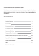
Product Overview GD 09 The perfect HTPC case for everyone Introduction The Grandia GD09 is a culmination of SilverStone’s decade-long experience in HTPC case design and manufacturing into a product that every PC enthusiast can enjoy.
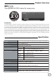
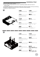
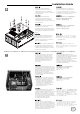
Disassemble Chart 5.25” DRIVE BAY X 1 OR 3.5” DRIVE BAY X 1 OR 2.5” DRIVE BAY X 2 TOP - COVER FILTER 3.5” DRIVE BAY X 1 OR 2.5” DRIVE BAY X 1 12025 FAN X 1 OR 8025 FAN (OPTION) PS2 - PSU (OPTION) EXPANSION SLOTS X 8 3.5” DRIVE BAY X 1 8025 FAN X 2 (OPTION) 12025 FAN X 1 12025 FAN X 1 (OPTION USB 3.0 X 2 + SPK + MIC 5.25” DRIVE BAY X 1 RESET - BUTTON POWER - BUTTON PICTURE FILTER ITEM SHOCK TANT - RING - YEL - GRAY Anti-vibration rings STANDOFF - 6 - 32 X 6.
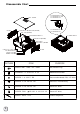
Installation Chart Before you begin, please make sure that you (1) have all components collected (2) check that all components do not have compatibility problems with each other or with the case (3) if possible, assemble the components outside the case first to make sure they are working (4) keep the motherboard manual ready for reference during installation (5) prepare a Philips screwdriver.
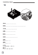
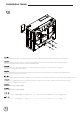
Installation Guide 3 Unscrew two screws from the center brace to remove it Lesen Sie die beiden Schrauben an der mittleren Halterung, nehmen Sie die Halterung heraus. Dévissez les deux vis de la barre centrale afin de la retirer. Desatornille dos tornillos del eje central para quitarlo. Svitare le due viti del gancio centrale per rimuoverlo. Открутите два шурупа на центральной скобе и выньте ее.
Installation Guide 4 Install power supply into the case. If you use a power supply with 120mm fan or bigger, we recommend installing it with the fan facing left (outwards). For more information regarding power supply size limitations, please refer to the component guide in later pages Falls Sie ein Netzteil mit einem 120 mm-Lüfter (oder größer) verwenden, empfehlen wir eine Installation, bei der der Lüfter nach links (außen) zeigt.
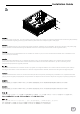
Installation Guide 5 Insert the I/O shield included with your motherboard into the rear I/O slot on the case Setzen Sie das mit Ihrem Motherboard gelieferte I/O-Blech in die Aussparungen an der Rückseite des Gehäuses ein, installieren Sie anschließend das Motherboard im Gehäuse. Insérez la plaque d'E/S inclus avec votre carte mère, puis installez la carte mère dans le boîtier Inserte el protector de E/S incluido en su placa base, luego instale la placa base en la carcasa.
Installation Guide 6 7 If required, install additional motherboard standoffs onto the motherboard tray, then install the motherboard into the case and secure with SCREW C При необходимости установите дополнительные опорные винты на лоток системной платы, затем установите системную плату в корпус и закрепите с помощью винта C If required, install additional motherboard standoffs onto the motherboard tray, then install the motherboard into the case and secure with SCREW C 請依需求將SCREW D 的主機板螺柱鎖 固於機殼,再將主機板
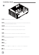
Installation Guide 8 Install 2.5” drive onto the floor of the case and secure with screws. Make sure drive connectors are facing the rear of the case Installieren Sie das 2,5 Zoll-Laufwerk im unteren Teil des Gehäuses; anschließend mit Schrauben fixieren. Stellen Sie sicher, dass die Laufwerksanschlüsse in Richtung Gehäuserückseite zeigen Installez le lecteur 2,5" dans la partie inférieure du châssis et attachez-le avec des vis.
Installation Guide 9 10 Use small bracket included in the accessories box to install 3.5” drive beneath the optical drive area Для установки 3,5-дюймового диска под оптическим приводом используйте малый кронштейн из пакета аксессуаров Verwenden Sie die mitgelieferte kleine Halterung zur Installation des 3,5-Zoll-Laufwerks unter dem Bereich des optischen Laufwerks 使用零件包內附小架, 安裝光碟機下方的3.
Installation Guide 11 Remove expansion slot covers as required, install expansion cards and secure with screws Entfernen Sie die Abdeckungen des Erweiterungssteckplatzes wie erforderlich; installieren Sie die Erweiterungskarten und sichern Sie mit Schrauben Retirez les caches des fentes d’extension si nécessaire, installez les cartes d'extension et attachez-les avec des vis.
Installation Guide 12 Install hard drive and optical drive to optical drive bracket as required. For more details on installation of this bracket, please refer to the guides in the later pages Installieren Sie Festplatte und optisches Laufwerk wie erforderlich in der Halterung für optische Laufwerke. Weitere Einzelheiten zur Installation dieser Halterung entnehmen Sie bitte den Anleitungen auf späteren Seiten Installez le disque dur et le lecteur optique sur le support de lecteur optique si nécessaire.
Installation Guide 13 Remove 5.25” drive bay cover if needed При необходимости снимите крышку отсека 5,25-дюймового диска Entfernen Sie die Abdeckung des 5,25-Zoll-Laufwerkseinschubs, falls erforderlich 移除需要安裝的5.25”檔板 Retirez le couvercle de la baie de lecteur 5,25" si nécessaire. 移除需要安装的5.25”檔板 Retire la cubierta de la bahía de dispositivos de 5,25” si lo necesita 必要ならば5.25”ドライブ ベイカバーを取外します。 Rimuovere la copertura dell’alloggio unità 5,25", se necessario 필요할 경우 5.25" 드라이브 베이 커버를 벗기십시오.
Installation Guide 15 16 Reinstall the optical drive bracket back into the case Установите кронштейн оптического привода в корпус Installieren Sie die Halterung für optische Halterungen wieder im Gehäuse 將光碟架裝回機殼 Réinstallez le support du lecteur optique dans le boîtier. 将光盘架装回机壳 Reinstale el bracket para dispositivo óptico de nuevo en la carcasa 光学ドライブ・ブラケッ トをケースに戻します。 Reinstallare il supporto dell'unità ottica sul telaio 광 브라이브 브래킷을 케이스에 도로 끼우십시오.
Installation Guide 17 Reinstall top cover back onto the case to complete installation Bringen Sie zum Abschluss der Installation die obere Abdeckung wieder am Gehäuse an Réinstallez le couvercle supérieur sur le boîtier pour terminer l'installation.
Connector definition (1) Front panel connector installation no polarity, so they can be connected in any orientation Power switch and reset switch installation guide: Please refer to the motherboard manuals for the motherboard’s “Front Panel Connector” or “System Panel Connector” pin definitio Power switch and reset switch have no polarity, so they can be connected in any orientation.
Connector definition (2) LED indicators installation guide Please refer to the motherboard manuals for the motherboard’s “Front Panel Connector ” or “System Panel Connector” pin definition.; the white/black wires are negative while other colors are positive wires. The Power LED wires are separate pins for compatibility with different motherboard pin definition so please make sure they are connected in the right polarity by referring to your motherboard manual.
Connector definition (3) Front I/O connector guide Below are the front I/O connectors pin definition, please also check your motherboard manual to cross reference with motherboard’s front I/O pin headers. SilverStone’s I/O connectors are in block type to simplify installation. Nachstehend finden Sie die Pinbelegung der vorderen E/A-Anschlüsse; bitte gleichen Sie zudem das Handbuch Ihres Motherboards mit den vorderen E/A-Pinzuweisungen ab.
Component size limitations The GD09 was designed to be compatible with standard sized or some larger components, please refer to the following guidelines for component selection and future upgrade considerations. (1) CPU cooler height limitation 138MM (A) 8MM 341MM 170MM (B) 88MM A. The GD09 has 138mm height limitation for CPU cooler and clearance of 8mm beyond the motherboard. If no optical drive is installed, there is 170mm of room from the front panel to the motherboard edge. B.
Component size limitations A. GD09 모델의 경우 CPU 쿨러의 높이가 138mm로 제한되며 메인보드까지 8mm의 여유가 있습니다. 광 드라이브를 설치하지 않은 경우 전면 패널에서 메인보드 가장자리까지의 공간은 170mm입니다. B. 광 드라이브 아래쪽 여유 공간은 88mm입니다. 광 드라이브 전면 구멍에서 메인보드 후면까지의 총 길이는 348mm이며 광 드라이브의 길이를 알고 있을 경우 광 드라이브 설치에 이용할 수 있는 공간을 쉽게 계산할 수 있습니다. A. GD09には、CPUクーラー高さ制限およびマザーボード上方限度8mmの余裕があります。光学ドライブをインストールしない場合、 フロントパネルからマザーボード端まで170mmの余地があります。 B. 光学ドライブ下方の余地は88mmです。 フロントの光学ドライブからマザーボード後部までの距離は合計で348mmであるので、光学ドライブの長さが既知であれば、光学ドライブにインス トール後に利用できるスペースを簡単に計算することができます。 A.
Component size limitations C. 이 그림은 170mm 길이의 광 드라이브가 장착된 LGA115X에 설치된 SilverStone AR02 CPU 쿨러의 모습입니다. 공기가 케이스 뒤쪽으로 배기되도록 AR02 팬을 방열판 후면에 설치해야 했습니다. 광 드라이브가 설치되지 않은 경우 전면을 향하게 팬을 설치하여 공기를 방열판으로 끌어들일 수 있습니다. 두 가지 팬 구성 모두에서 GD09의 중앙 죔쇠가 AR02의 방열판을 건드리지 않고 간신히 지나갈 정도입니다. C. 図には170mm長の光学ドライブをインストールしたLGA115Xプラットホームに設置されたSilverStone AR02 CPUクーラーが示されています。 AR02のファンは、ケース後方へ空気を排出するよう、ヒートシンク後方に設置する必要があります。光学ドライブをインストールしない場合、 ファンはフロントに向かってヒートシンクに空気を吸い込むよう設置できます。双方のファン構成では、GD09のセンターブレースは、ぎりぎり でAR02のヒートシンクの余地に収まります。 C.
Component size limitations A: Limitación de profundidad: La profundidad máxima de la FA es de 180mm si el ventilador de 120mm del lado izquierdo de la carcasa y los dispositivos de 2,5” de la parte inferior están instalados. Las FA de 180mm totalmente modulares como los modelos Strider Gold Evolution de SilverStone tienen conectores que interfieren con los ventiladores más grandes, luego en este caso solo se puede instalar un ventilador de 80mm.
Component size limitations (3) Graphics card/expansion card length limitation and relationship with center drive (B) A: Length limitation GD09 supports maximum of 12.2 inches long graphics cards B: Drive connector If graphics card is installed in the first expansion slot and there is a drive installed to the right, we recommend using 90 degree angled SATA connector with a height of no more than 16mm A: Längenbeschränkung Das GD09 nimmt bis 12.2 lange Grafikkarten auf.
Component size limitations (4) Motherboard width limitation (A) (B) A: Illustration: ASUS Rampage III Extreme is wider than standard ATX size of 9.6 inches Although GD09 does not support true Extended ATX (SSI-EEB) motherboards, it does support ATX models up to 11 inches wide. Motherboard standoff holes are included to support SSI-CEB so high-end enthusiasts ATX boards such as ASUS Rampage III Extreme or EVGA X58 SLI Classified, which are up to 10.6 inches wide, can fit comfortably inside GD09.
Component size limitations A: Иллюстрация: ASUS Rampage III Extreme шире стандартной платы ATX размером 9,6 дюйма. Хотя GD09 не поддерживает оригинальные системные платы Extended ATX (SSI-EEB), он поддерживает модели ATX шириной до 11 дюймов. Отверстия под опорные винты системной платы предназначены для поддержки SSI-CEB, благодаря чему поклонники плат ATX, таких как ASUS Rampage III Extreme или EVGA X58 SLI Classified шириной до 10,6 дюйма, могут легко разместить их в корпусе GD09.
Recommended cooling device setup and selection (1) CPU cooler recommendation (A) A: If you are installing a tower-style CPU cooler such as SilverStone’s AR02, we recommend mounting its fan to blow into the heatsink and toward the rear of the case if there is no interference. A: Falls Sie einen CPU-Kühler im Tower-Stil, wie SilverStones AR02, installieren, sollten sie seinen Lüfter so montieren, dass er in den Kühlkörper und Richtung Rückseite des Gehäuses bläst, falls sich nichts im Weg befindet.
Recommended cooling device setup and selection (C) C: When choosing a graphics card, we recommend models that have fan blowing exhaust air to the rear slot, this will ensure smooth and efficient airflow within the GD09 for maximum cooling performance.
Recommended cooling device setup and selection (3) Recommendation for fan installation *FQ121, 120mm, 1000 ~ 1800rpm *AP122, 120mm, 1200rpm By default, GD09 includes 1 fan to meet basic cooling requirements. If you like to add more fans to further improve cooling performance, we recommend installing them as intake fans in the remaining fan slots except the rear.
Upgrade and maintenance (1) Fan filter removal steps Illustration: An example of a GPU cooler that is filled with dust and has lost most of its cooling performance GD09’s positive air pressure design is an effective configuration that will reduce dust buildup inside the case. Small air particles or lint will accumulate over time on intake filters instead of on the components inside the case.
Upgrade and maintenance (2) Extra expansion slot GD09 has an extra expansion slot for use with device or short expansion card such as extra motherboard I/O, fan controller, SilverStone’s ClearCMOS, or daughter board (e.g. ASUS Xonar HDAV1.3), Please refer to the following illustration for installation.
Upgrade and maintenance (3) Multi-purpose drive cage design Below illustrations shows corresponding mounting points for each drive slot: 1. 3. 2. 4. 5. There is no installation order if a 5.25” device is installed on top of the optical drive cage with 3.5” drive installed underneath.
Upgrade and maintenance No hay orden de instalación si se instala un dispositivo de 5,25” sobre la carcasa para dispositivo óptico con un dispositivo de 3,5” instalado debajo.
Protect Your Computer Kensington Security Slot A lock and cable can be purchased on the market for use with the Kensington security slot located on rear of GD09 to prevent removal of the entire computer or top cover. Caution: Please check for compatibility before purchasing the lock and cable for use with GD09’s Kensington security slot. Durch ein Kensington-Schloss am GD09 kann verhindert werden, dass das gesamte System oder die obere Abdeckung entfernt wird.
Q&A Q: I found that the GD09 is too large to fit in my home theater cabinet after installing the display output adapter. How can I solve this problem? A: Please use the adapter cable as a replacement for the display output adaptor. The cable can be bent in any direction to ensure that the GD09 fits comfortably inside your home theater cabinet. Q: Das GD09 ist zu groß; nach der Installation des Anzeigeausgangsadapters passt es nicht mehr in meinen Heimkinoschrank.
Warranty information This product has a limited 1 year warranty in North America and Australia. For information on warranty periods in other regions, please contact your reseller or SilverStone authorized distributor. Warranty terms & conditions 1. Product component defects or damages resulted from defective production is covered under warranty. Defects or damages with the following conditions will be fixed or replaced under SilverStone Technology’s jurisdiction.