1
2
3
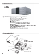
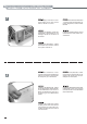
1 Unscrew four case screws to remove case cover Desatornille cuatro tornillos de la caja para poder retirar la cubierta Lösen Sie die vier Schrauben an der hinteren Abdeckung und entfernen Sie diese Svitare quattro viti del pannello superiore del case per rimuoverlo Dévissez les quatres vis pour retirer le capot du boîtier 2 Unscrew four case screws to remove case cover Desatornille cuatro tornillos de la caja para poder retirar la cubierta Lösen Sie die vier Schrauben an der hinteren Abdeckung und
3 Power Supply Installation-Insert power supply into the case, secure with four # 6 -32 x 6 screws Instalación de la fuente de alimentación - Inserte la fuente de alimentación en la caja, asegúrela con cuatro tornillos #6-32x6 Installation des Netzteils - Setzen Sie das Netzteil in das Gehäuse ein und befestigen Sie es mit vier #6-32 x 6 Schrauben Installazione dell’alimentatore- Inserire l’alimentatore nel case, fissare con 4 viti #6-32x6 Installation de l'alimentation - Insérez l'alimentation dans le
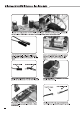
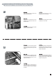
5 Place motherboard into the case and secure with M3 screws Coloque la placa base en la caja y asegúrela con tornillos M3 Setzen Sie ihr Mainboard in das Gehäuse ein und sichern Sie es mit M3 Schrauben Collocare la scheda madre nel case e fissarla con le viti M3 Placez votre carte mère dans le boîtier et fixez-la avec des vis M3 6 Remove 3.5” drive bracket located behind the acrylic front panel by unscrewing two screws on top of the bracket Elimine el bracket de la unidad de 3.
7 Prepare your hard drive for installation Prepare el disco duro para su instalación Bereiten Sie ihre Festplatte für die Installation vor Preparare l’hard disk per l’istallazione Préparation de l'installation des disques durs 8 Use #6-32 x 6 screws to install hard drive into the 3.5” drive bracket, up to three hard drives can be installed Use tornillos #6-32x6 para instalar el disco duro en el bracket de unidad de 3.5”.
After hard drives are installed, place the 3.5” drive bracket back into the case and secure with screws Después de haber instalado los discos duros, coloque de nuevo el bracket de las unidades de 3.5” en la caja y asegúrelo con tornillos Setzen Sie die 3.5” Halterung wieder in das Gehäuse ein und befestigen Sie diese nachdem Sie die Festplatte in der Halterung installiert haben Dopo aver installato gli hard disk, ricollocare il supporto da 3.
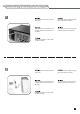
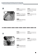
11 Remove right-front panel slowly and carefully as indicated in the photo Saque con cuidado y lentamente el panel frontal como se muestra en la foto Entfernen Sie die rechte Front-Abdeckung langsam und vorsichtig wie auf der Abbildung gezeigt Rimuovere la parte destra del pannello frontale lentamente e con cura come indicato nella foto. Retirez le côté droit du panneau frontal doucement et avec précautions comme indiqué sur la photo 12 Insert optical drive into the top slot of the 5.
13 Insert the second optical drive or other 5.25” drive bay device intothe bottom slot Inserte la segunda unidad óptica u otro dispositivo en la ranura inferior de la bahía de discos de 5.25” Setzen Sie das zweite optische Laufwerk oder ein anderes 5.25” Laufwerk in den unteren Einschub ein Inserire un secondo drive ottico o un altro dispositivo da 5.25” nello slot inferiore. Insérez le second lecteur optique ou un autre appareil 5.25” dans l'emplacement inférieur 14 Secure both 5.
15 When reinstalling right-front panel back onto the case, make sure the push-pin on the panel is aligned with the catch in the case. Cuando vuelva a poner el panel frontal en la caja, cuide que la varilla del panel esté alineada con la base de la caja Achten Sie beim Einsetzen der rechten Front-Abdeckung darauf das der Push-Pin richtig ausgerichtet ist.
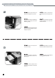
17 A second 3.5” drive bracket is located beneath the 5.25” drive bays with room for one more hard drive. It can be taken out of the case easily with a screw removed Hay un segundo bracket para dispositivos de 3.5” bajo la bahía de 5.25” con espacio para un disco duro más. Se puede sacar con facilidad de la caja si se quita un tornillo Unter der 5.25” Halterung befindet sich eine zusätzliche 3.5” Halterung, die Platz für eine zusätzliche Festplatte bietet.
19 Secure reinstalled bracket with screw Asegure el bracket con el tornillo Schrauben Sie die Halterung wieder fest Fissare il supporto con la vite Fixez le casier réinstallé avec une vis 20 For extra EMI protection, route front panel cables through the included wire ring Para una protección EMI extra, haga pasar los cables del panel frontal a través del anillo incluido Führen Sie die Kabel der Front-Abdeckung durch den Kabelring um eine besseren Schutz vor elektromagnetischen Wellen zu erhalten P
22 Insert the connector from the hotkey module into a USB pin header on your motherboard (please refer to your motherboard manual for connection information, the side with the black wire is the ground connection) Inserte el conector etiquetado “HOTKEY” del módulo de tecla de acceso rápido en el conector USB de pines de su placa base (por favor, consulte el manual de su placa base para información sobre cómo hacer la conexión, el lado del cable negro es la tierra) Schließen Sie den Stecker mit der Aufschr
May, 2008