Six PCI-E 6pin and dual PCI-E 8pin connectors
1. GENERAL This is the specification of Model OP1000-Evolution; it is intended to describe the functions and performance of the subject power supply. This PS/2 1000 watts switching power supply with Active PFC (Power Factor Correction) capability, meets EN61000-3-2 and equips Full Range Input features. 2. AC INPUT SPECIFICATIONS 2.1 AC Input Voltage, Frequency and Current ( Rating: 100V-240Vac, 47-63Hz, 15-7.
ŐőIJıııĮņ 2.3 Input Power Factor Correction ( Active PFC) 2.4 Input Current Harmonics When the power supply is operated in 90-264Vac of Sec. 2.1, the input harmonic current drawn on the power line shall not exceed the limits set by EN61000-3-2 class “D” standards. The power supply shall incorporate universal power input with active power factor correction. 2.5 AC Line Dropout An AC line dropout of 15mS or less shall not cause any tripping of control signals or protection circuits.
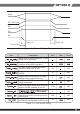
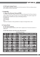
Ripple and Noise shall be measured using the following methods: 3.3 Timing Requirements These are the timing requirements for the power assembly operation. The output voltages must rise from 10% to within regulation limits (Tvout_rise) within 5 to 70mS. The +5V, +3.3V and +12V output voltages should start to rise at about the same time. All outputs must rise monotonically. The +5V output needs to be greater than the +3.3V output during any point of the voltage rise.
ŐőIJıııĮņ Vout V1 10% Vout V2 V3 V4 Tvout_on Tvout_off Tvout_rise Figure 1 : Output Voltage Timing Item Description Min Max Units Delay from AC being applied to +5VSB being within regulation. Delay from AC being applied to all output voltages being within regulation All main output voltage stay within regulation after loss of AC 16 mS Delay from loss of AC deassertion of PWOK. 15 mS Delay from PSON# active to output voltage within regulation limits.
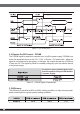
Figure 2 : Turn On/Off Timing 3.4 Remote On/Off Control : PSON# The PSON# signal is required to remotely turn on/off the power supply. PSON# is an active low signal that turns on the +5V, +3.3V, +12V and –12V power rails. When this signal is not pulled low by the system, or left open, the outputs (except the +5VSB and V bias) turn off. This signal is pulled to a standby voltage by a pull-up resistor internal to the power supply. Accepts an open collector/drain input from the system.
ŐőIJıııĮņ 3.6 +5VSB (Standby) The +5VSB output is always on (+5V Standby) when AC power is applied and power switch is turned on. The +5VSB line is capable of delivering at a maximum of 4A for PC board circuit to operate. 4. Protection Protection circuits inside the power supply shall cause only the power supply’s main outputs to shutdown.
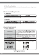
4.3 Short Circuit Protection The power supply shall shut down in a latch off mode when the output voltage is short circuit. 5. Environmental Requirements 5.1 Temperature Operating Temperature Range: 5.2 Humidity 6. Agency Requirements 6.1 Safety Certification.
ŐőIJıııĮņ 6.2 AC Input Leakage Current Input leakage current from line to ground will be less than 3.5mA rms. Measurement will be made at 240 VAC and 60Hz. 7. Reliability 7.1 Mean Time Between Failures (MTBF) The MTBF of the power supply shall be calculated utilizing the Part-Stress Analysis method of MIL217F or Bell core RPP.
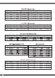
Pin Signal Color Size Pin Signal Color 1 COM Black 18 AWG 5 +12 VDC Yellow 16 AWG 2 COM Black 18 AWG 6 +12 VDC Yellow 16 AWG 3 COM Black 18 AWG 7 +12 VDC Yellow 16 AWG 4 COM Black 18 AWG 8 +12 VDC Yellow 16 AWG Pin Signal Color Size Pin Signal Color 1 COM Black 18 AWG 3 +12 VDC Yellow 16 AWG 2 COM Black 18 AWG 4 +12 VDC Yellow 16 AWG Pin Signal Color Size Pin Signal Color Size Signal Color Size 1 3 2 4 Pin Signal Color Size Pin
ŐőIJıııĮņ 8PIN PCI Express connector Pin Signal Color Size 1 5 2 6 3 7 4 8 9. Physical Characteristics Size 9.
NO:G11205720