Installation and system optimization guide: The following manual and guides were carefully prepared by the RAVEN engineering team to help you maximize the potential of your SilverStone product. Please keep this manual for future reference when upgrading or performing maintenance on your system. A copy of this manual can also be downloaded from our website at: http://www.silverstonetek.com 1 Specifications P.2 Disassemble Chart P.3 Installation Guide P.5 Connector definition P.
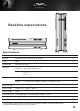
Redefine expectations Specifications Model SST-RVZ01B (black) Material Reinforced plastic outer shell, steel body Color Black Motherboard Mini-DTX, Mini-ITX Drive Bay Exposed Slim slot-loading optical x 1 Internal 3.5" x 1 2.5” x 3 Cooling System Top 1 x 120mm fan, 1500rpm, 18dBA Bottom 1 x 120mm fan, 1500rpm, 18dBA ; 1 x 120mm fan slot 2 Expansion Slot Front I/O Port USB 3.0 x 2 , audio x 1, MIC x 1 Power Supply SFX Expansion Card Compatible with 13.3” long, width restriction – 5.
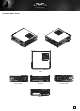
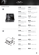
Disassemble Chart FAN FILTER X 1 2.5” HDD X 2 GRAPHICS CARD SUPPORT BRACKET SLOT - LOADING OPTICAL DRIVE (OPTION) TOP COVER HDD CAGE 2.5” HDD X 1 12015 FAN X 1 FAN FILTER X 2 MINI - ITX (OPTION) 12015 FAN X 1 USB 3.0 + SPK + MIC POWER BUTTON 3.
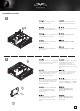
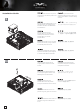
Disassemble Chart TOP LEFT SIDE FRONT RIGHT SIDE BACK 4
lnstallation Guide 1 Unscrew the screws from the rear of the chassis then remove the top cover. Ослабьте два винта на задней панели корпуса и снимите верхнюю крышку. Lösen Sie die beiden Schrauben von der Rückseite des Gehäuses, entfernen Sie dann die obere Abdeckung. 섀시 후면에 있는 두 개의 나사를 푼 다음 상단 커버를 분리합니다. Dévissez les deux vis à l'arrière du châssis puis enlevez le couvercle supérieur.
lnstallation Guide 3 4 Unscrew the screws from PSU bracket then remove it. Отвинтите винт кронштейна блока питания и извлеките его. Lösen Sie zum Abnehmen die Schraube an der Netzteilhalterung. PSU 케이스의 나사를 풀어 케이스를 분리합니다. Dévissez les vis du support du bloc d'alimentation pour le retirer. PSUケージのネジを緩めて取 り外します。 Afloje el tornillo de la carcasa de la FA para retirarla. 鬆開電源架的螺絲,取下電源架 Allentare la vite sulla staffa PSU per rimuoverlo. 松开电源架的螺丝,取下电源架 If you want to mount a 2.
lnstallation Guide 5 If you want to use SilverStone NT06-PRO or other similar CPU cooler, please relocate the top panel 120mm fan to the bottom vent near the graphics card area. Falls Sie den SilverStone NT06-PRO oder einen vergleichbarenCPU-Kühler verwenden möchten, entfernen Sie bitte den 120-mm-Lüfter an der oberen Blende und bringen ihn an den unteren Belüftungsöffnungen in der Nähe des Grafikkartenbereichs an.
lnstallation Guide 7 8 We recommend at this point connecting all the necessary cables including the SATA cables to the motherboard. На этом этапе мы рекомендуем подключить к системной плате все необходимые кабели, включая кабели SATA. Wir empfehlen, an diesem Punkt alle erforderlichen Kabel, einschließlich der SATA-Kabel, am Motherboard anzuschließen. 이 시점에서 SATA 케이블을 포함하여 필요한 모든 케이블을 메인보드에 연결할 것을 권장합니다.
lnstallation Guide Place the PSU bracket on top of the chassis then connect the power cord to the PSU. Установите кронштейн блока питания в верхней части корпуса и подключите кабель питания к блоку питания. Bringen Sie die Netzteilhalterung im oberen Bereich des Gehäuses an; schließen Sie dann das Netzkabel am Netzteil an. PSU 브래킷을 섀시 상단에 위치시킨 후 전원 코드를 PSU에 연결합니다. Placez le support du bloc d'alimentation sur le dessus du châssis puis branchez le cordon d'alimentation sur le bloc d'alimentation.
lnstallation Guide Remove expansion slot cover and install graphics card into the graphics card support bracket. 11 Entfernen Sie die Abdeckung des Erweiterungssteckplatzes und installieren die Grafikkarte in der Grafikkartenhalterung. 확장 슬롯 커버를 벗기고 그래픽 카드를 그래픽 카드 지지 브래킷에 설치합니다. Retirez le couvercle de la fente d'expansion et installez la carte graphique dans le support de la carte graphique.
lnstallation Guide 13 14 11 Install 2.5”HDD/SSD and slim slot-loading optical drive onto the graphics card support bracket. Установите 2,5-дюймовый жесткий или твердотельный диск и тонкий оптический привод с загрузкой через слот на крепежный кронштейн графической карты. Installieren Sie eine 2,5-ZollFestplatte/SSD und ein optisches Slot-in-Laufwerk an der Grafikkartenhalterung. 2.5”HDD/SSD와 슬림형 슬롯 로딩 방식 광드라이브를 그래픽 카드 지지 브래킷에 설치합니다.
lnstallation Guide Make sure all the cables are properly connected. Проверьте правильность подключения всех кабелей. Achten Sie darauf, dass sämtliche A K Kabel richtig angeschlossen sind. 모든 케이블이 제대로 연결되었는지 확인하십시오. Vérifier que tous les câbles sont V ccorrectement branchés. 全てのケーブルが確実に接続されて いることを確認します。 Asegúrese de que todos los cables A están conectados apropiadamente e 確定所有線材都已正確的安裝 Assicurarsi che tutti i cavi siano collegati correttamente.
lnstallation Guide 17 13 Depending on requirement or preference, adhere four rubber stands for horizontal use or install the rubber pads for vertical use. Corresponding RAVEN logo for each orientation are included for installation. В зависимости от ваших требований или предпочтений установите четыре резиновых стойки для использования в горизонтальном положении или четыре резиновых прокладки для использования в вертикальном положении.
Connector definition (1) Front Panel Connectors Guide: Front panel connector installation no polarity, so they can be connected in any orientation A.Power switch and reset switch installation guide: Please refer to the motherboard manuals for the motherboard’s “Front Panel Connector” or “System Panel Connector” pin definitio Power switch and reset switch have no polarity, so they can be connected in any orientation.
Connector definition (1) Front Panel Connectors B:LED indicators installation guide Please refer to the motherboard manuals for the motherboard’s “Front Panel Connector ” or “System Panel Connector” pin definition.; the white/black wires are negative while other colors are positive wires. The Power LED wires are separate pins for compatibility with different motherboard pin definition so please make sure they are connected in the right polarity by referring to your motherboard manual.
Connector definition (2) Front I/O connector guide Below are the front I/O connectors pin definition, please also check your motherboard manual to cross reference with motherboard’s front I/O pin headers. SilverStone’s I/O connectors are in block type to simplify installation. Nachstehend finden Sie die Pinbelegung der vorderen E/A-Anschlüsse; bitte gleichen Sie zudem das Handbuch Ihres Motherboards mit den vorderen E/A-Pinzuweisungen ab.
Component size limitations The RVZ01 can accommodate all standard size components and even some that are out of spec, please refer to the following guidelines for component selection and future upgrade considerations. 11 (1) CPU cooler height limitation 7 83 A.Height limitation: The RVZ01 has 83mm height limitation for CPU cooler B.Upper boundary: the cooler can protrude 11mm over the motherboard’s top edge. C.Front boundary: The clearance toward the front of the chassis is 7mm. A.
Component size limitations (2) PSU limitation The RVZ01 supports only standard SFX power supply with a 100mm depth. In the illustration, the PSU is situated in the front part of the chassis with the 90 degrees connector extension cable installed. The extension cable shall not exceed the upper or the lower boundary. Der RVZ01 unterstützt SFX-Standardnetzteile mit einer Tiefe von 100 mm.
Component size limitations (3) Graphics card/expansion card length limitation A. Length limitation The RVZ01 can support 13”(330mm) consumer level graphics cards. Please contact us if you find a card that does not fit. Das RVZ01 nimmt bis zu 330 mm lange Grafikkarten auf. Bitte wenden Sie sich an uns, falls Sie keine passende Karte finden können. Le RVZ01 peut supporter la plupart des cartes graphiques du marché de 13" (330mm). Veuillez nous contacter si vous trouvez une carte qui ne correspond pas.
Component size limitations (3) Graphics card/expansion card length limitation B. Width limitation (i) The standard width for graphics card is 4.38”. (11.12cm) (ii) With the graphics card holder installed, the maximum allowable width for graphics card is 5.18”. (13.16cm) (iii) Without the graphics card holder, the maximum allowable width for graphics card is up to 5.88”. (14.93cm) (i)Die Standardbreite bei Grafikkarten beträgt 11,12 cm.
Component size limitations (3) Graphics card/expansion card length limitation C. Thickness limitation (i)Calculated from the bottom of the graphics card PCB to the top, the total thickness limitation is 68mm. (ii)With the standard 34.8mm-thick dual slot graphics card installed, the maximum thickness of the fans is 32mm. (iii)With the standard 14.5mm-thick single slot graphics card and the included 15mm-thick fans installed, the maximum thickness of the water cooling radiator is 38mm.
Component size limitations (3) Graphics card/expansion card length limitation (i)Ограничение по толщине от нижнего до верхнего края печатной платы составляет 68 мм. (ii)При установке стандартной двусторонней графической карты толщиной 34,8 мм максимальная толщина вентиляторов составляет 32 мм. (iii)При установке стандартной одногнездовой графической карты толщиной 14,5 мм и вентиляторов толщиной 15 мм максимальная толщина радиатора с водяным охлаждением составляет 38 мм.
Optimal Thermal Performance Layout (1) To improve thermal performance, we recommend using SilverStone NT06-PRO CPU cooler. A A. The NT06-PRO must be installed rearward on motherboard such as ASUS P8Z77-I DELUXE. Please install cooler with caution for this type of configuration. A. Der NT06-PRO muss rückwärts gerichtet am Motherboard, wie dem ASUS P8Z77-I DELUXE, installiert werden. Bitte installieren Sie den Kühler bei diesem Konfigurationstyp entsprechend vorsichtig. A.
Optimal Thermal Performance Layout (1) To improve thermal performance, we recommend using SilverStone NT06-PRO CPU cooler. B B.The CPU socket on Z87 motherboard is closer to the edge. We recommend installing NT06-PRO toward left side. B.Der CPU-Sockel am Z87-Motherboard befindet sich näher am Rand. Wir empfehlen, den NT06-PRO nach links ausgerichtet zu installieren. B.La prise de CPU sur la carte mère Z87 est plus près du bord. Nous vous recommandons d'installer la NT06-PRO vers le côté gauche. B.
Optimal Thermal Performance Layout (1) To improve thermal performance, we recommend using SilverStone NT06-PRO CPU cooler. C C. Intel reference Mini-ITX motherboard layout has CPU socket next to PCI Express slot, NT06-PRO should have no installation problems with this layout. C. Das Intel Mini-ITX-Motherboard-Layout hat den CPU-Sockel neben dem PCI-Express-Steckplatz; der NT06-PRO sollte keine Installationsprobleme mit diesem Layout haben. C.
Optimal Thermal Performance Layout (1) To improve thermal performance, we recommend using SilverStone NT06-PRO CPU cooler. D.For additional information on NT06-PRO dimensions, please visit our website. E.Theoretically, NT06-PRO’s heat pipes may not work optimally when installed facing downward. However, during RVZ01’s thermal testing phase, we did not detect any performance difference among different orientation when using a 95W LGA115X based CPU.
Optimal Thermal Performance Layout (2) If you use a high-end graphics card, the pre-installed case fan on the bottom vent below graphics card should provide plenty of cooling for them. If you use graphics card with omni-direction or open air cooler, we recommend having two case fans on the bottom vents. Wenn Sie eine Grafikkarte mit omnidirektionalem und Open-Air-Kühler verwenden, empfehlen wir zwei Gehäuselüfter an den unteren Belüftungsöffnungen.
Optimal Thermal Performance Layout (3) Storage device temperature A.The RVZ01 is designed as a high performance gaming platform, we recommend using SSD as the primary storage device as they are more heat-resistant. B. By the design, RVZ01’s case fans are not designed for cooling 3.5” hard drives. We recommend using low RPM hard drives or models with better heat resistance. If you’re not still satisfied with the thermal performance, we recommend placing the RVZ01 in the vertical position. A.
Optimal Thermal Performance Layout (4)Vertical/horizontal placement A. Because most vents are situated on the bottom, placing the RVZ01 vertically will result in better temperature than in horizontal position. B. When using the case horizontally, please be sure of adhering rubber stands to the bottom. A. Da sich die meisten Belüftungsöffnungen an der Unterseite befinden, führt die vertikale Aufstellung des RVZ01 zu einem besseren Temperaturergebnis als die horizontale Aufstellung. B.
Optimal Thermal Performance Layout (5) Recommendation for water cooling A.When sufficient budget is allowed, we recommended using DIY water cooling. B. A Laing DDC pump can be mounted onto the center 2.5” brace. The mounting holes are shown in the illustration above. C. If you plan to use water cooling radiator in the graphics card area, we recommend using waterblock with full-cover for their overall lower the thickness. A.Wenn das Budget ausreicht, empfehlen wir den Einsatz einer DIY-Wasserkühlung. B.
Optimal Thermal Performance Layout (5) Recommendation for water cooling D.A dual, stacked power connector housing shown circled on the top of the example photo may interfere with the water cooling radiator; the dual-slot display output connectors shown in the lower circle on the other hand, will not have any interference issues. D.
Optimal Thermal Performance Layout (5) Recommendation for water cooling E F E. As illustrated above, the indicated numbers are the clearance when two 120mm fans are installed. F. The clearance above the CPU area is illustrated above. The additional clearance toward the rear is reserved for the space required by top cover installation. The height limit for the CPU cooler is 83mm, a figure that is also sufficient for liquid cooler’s waterblock and radiator. E.
Optimal Thermal Performance Layout (6) Cable routing There is some space between the front panel and the side of the graphics card reserved for the cable routing. Es befindet sich zur Kabelführung etwas Platz zwischen der Frontblende und der Seite der Grafikkarte. Il y a un certain espace entre le panneau avant et le côté de la carte graphique réservé pour le cheminement des câbles.
Maintenance and upgrade (1) Fan filter removal guide The RVZ01’s positive air pressure design is an effective configuration that will reduce dust buildup inside the case. Small air particles or lint will accumulate over time on intake filters instead of on the components inside the case. To maintain excellent cooling performance for years to come, we recommend cleaning all fan filters regularly every three months or half a year (depending on your environment).
Maintenance and upgrade (1) Fan filter removal guide El diseño de presión de aire positiva de la RVZ01 es una configuración efectiva que reducirá la acumulación de polvo dentro de la carcasa. Pequeñas partículas de polvo ó pelusa se irán acumularán con el transcurso del tiempo en los filtros de entrada en lugar de en los componentes del interior de la carcasa.
Maintenance and upgrade (2) Fan removal guide 34 The fan on the top cover can be dismounted after removing the top cover. Сняв верхнюю крышку, можно демонтировать установленный на ней вентилятор. Der Lüfter an der oberen Blende kann nach Entfernung der oberen Blende abgenommen werden. 상단 커버에 있는 팬은 상단 커버를 벗긴 후 탈거할 수 있습니다. Le ventilateur sur le couvercle supérieur peut être enlevé après avoir enlevé le couvercle supérieur.
Maintenance and upgrade (2) Fan removal guide 하단 통풍구에 있는 팬을 떼어내려면 먼저 그래픽 카드 홀더를 분리해야 합니다. 팬을 떼어내기 전에 필터를 분리할 것을 권장합니다.
Protect Your Computer 켄싱턴 보안 슬롯에 사용할 수 있는 자물쇠와 케이블은 별도로 구입 하실 수 있으며, RVZ01의 뒤쪽을 잠그므로, 컴퓨터 전체의 사이드 패널을 제거 할 수 없게 해 줍니다. 주의: RVZ01용 켄싱터 보안 잠금 장치를 구입하기전에 호환성을 확인하시기 바랍니다.
Q&A D: RVZ01 entra nel Sugo Pack? R: Sì. E rimane altro spazio! D: NT06-PRO può essere utilizzato senza ventilatore in RVZ01? R: Noi non lo consigliamo. D: Tutto è installato correttamente, perché non si avvia? R: Se il PSU dispone di un interruttore CA, assicurarsi che l'interruttore sia in posizione "ON". Вопрос: Корпус RVZ01 вмещается в сумку Sugo? Ответ: Да, и еще остается свободное место! Вопрос: Можно ли NT06-PRO использовать без вентилятора в корпусе RVZ01? Ответ: Мы не рекомендуем это делать.
Warranty Information This product has a limited 1 year warranty in North America and Australia. For information on warranty periods in other regions, please contact your reseller or SilverStone authorized distributor. Warranty terms & conditions 1. Product component defects or damages resulted from defective production is covered under warranty. Defects or damages with the following conditions will be fixed or replaced under SilverStone Technology’s jurisdiction.