
User guide

03
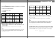
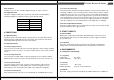
ST70F-ES, ST60F-ES provides an efficiency of >80% when measured at full load
under 115V/60Hz and 230V/50Hz condition.
Maximum continuous total DC output power should not exceed 700W.
Maximum continuous combined load on +3.3VDC and +5VDC outputs shall
not exceed 150W.
Maximum combined load on 12V outputs shall not exceed 552W.
NOTE:
Noise test should be measured with 20 MHz bandwidth frequency oscilloscope.
The output terminal shall add a tantalum capacitor of 10uF in parallel with a
ceramic capacitor of 0.1uF.
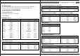
Output
Voltage
1. +5V 0.2A
2. +12V 0.6A
4. -12V
5. +5Vs
6. +3.3V
0.0A
0.0A
0.1A
25A
46A
0.3A
2.5A
25A
--
--
--
--
--
±5%
±5%
±5%
±10%
±5%
70mV
120mV
150mV
70mV
70mV
Load
MIN
Peak Regulation
Range
MAX
Ripple
P-P Max
2.5 Efficiency
3.1 Normal Operation Output
3.1.1 ST70F-ES
3. OUTPUT CHARACTERISTICS
04
STRIDER ST1000STRIDER ST1000-NV
Strider Essential Series
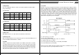
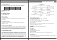
Maximum continuous total DC output power should not exceed 600W.
Maximum continuous combined load on +3.3VDC and +5VDC outputs shall
not exceed 150W.
Maximum combined load on 12V rails outputs shall not exceed 504W.
NOTE:
Noise test should be measured with 20 MHz bandwidth frequency oscilloscope.
The output terminal shall add a tantalum capacitor of 10uF in parallel with a
ceramic capacitor of 0.1uF.
The PSON# signal is required to remotely turn on/off the power supply, PSON#
is an active low signal that turns on the output power rails. When this is not pulled
low by the system, or left open, the outputs (except the +5VSB) turn off. This signal
is pulled to a standby voltage by a pull-up resistor internal to the power supply.
TTL level "H" 2.0 V - 5.25 V
"L" 0.0 V – 1.0 V
Output
Voltage
1. +5V 0.2A
2. +12V 0.6A
4. -12V
5. +5Vs
6. +3.3V
0.0A
0.0A
0.1A
25A
42A
0.3A
2.5A
25A
--
--
--
--
--
±5%
±5%
±5%
±10%
±5%
70mV
120mV
120mV
70mV
70mV
Load
MIN
Peak Regulation
Range
MAX
Ripple
P-P Max
3.1.2 ST60F-ES
3.2 Remote On/Off Controlled mode