STRIDER GOLD S SERIES SST-ST85F-GS /SST-ST75F-GS World’s smallest, full-modular ATX power supplies Compact design with a depth of 150mm for easy integration 80 PLUS Gold certification 100% modular cables 24/7 continuous power output with 40℃ operating temperature Class-leading single +12V rail Strict ±3% voltage regulation and low ripple & noise Silent running 120mm fan with 18dBA minimum O
SilverStone Strider Gold ST85F-GS ST75F-GS ATX12V / EPS 12V Switching Power Supply With Active PFC 80Plus Gold PS/2 This specification describes the requirements of 750W,850Watts switching power supply with an stretch ATX form-factor and EPS 12V, +5V standby voltage,remote on/off control, full range line input capability and forced air cooling characteristics. 1. AC INPUT 1.1 AC input requirements The input voltage, current, and frequency requirements for continuous operation are stated below.
ST85F-GS / ST75F-GS 1.2 Inrush current regulation The power supply must meet inrush requirements for any rated AC voltage, during turn on at any phase of AC voltage, during a single cycle AC dropout condition, during repetitive ON/OFF cycling of AC, and over the specified temperature range (Top). The peak inrush current shall be less than the ratings of its critical components (including input fuse, bulk rectifiers, and surge limiting device). 2. DC OUTPUT 2.
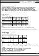
2.2.2: SST-ST85F-GS Load Range Parameter Min Nom. Max Unit +3.3V 0.5 - 22 Amps +5V 0.3 - 25 Amps +12V 1 - 70 Amps -12V 0 - 0.3 Amps 0.1 - 3.5 Amps +5VSB 1.Maximum continuous total DC output power should not exceed 850W. 2.Maximum c.ontinuous combined load on +3.3VDC and +5VDC outputs shall not exceed 150W. 3.Maximum combined current for the +12V outputs shall be 70A(840W). 4.When +12V is load to 28A , -12V minimum load is 0.02A. 5.
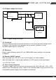
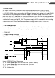
ST85F-GS / ST75F-GS 2.3.3 Ripple voltage test circuit Power Supply AC H o t V out 10uF V re tu rn AC N e u tra l 0 .1 u F Load AC G ro u n d S cope Figure 1. Ripple voltage test circuit 2.4 Overshoot Any overshoot at turn on or turn off shall be less 10% of the norminal voltage value, all outputs shall be within the regulation limit of section 2.0 before issuing the power good signal of section 5.0. 2.
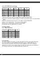
SST-ST75F-GS Voltage Over Current Limit (Iout limit) +12V 65A minimum; 95A maximum +5V 28A minimum; 45A maximum +3.3V 24A minimum; 40A maximum SST-ST85F-GS Voltage Over Current Limit (Iout limit) +12V 72A minimum; 105A maximum +5V 28A minimum; 45A maximum +3.3V 24A minimum; 40A maximum 3.2 Over Temperature Protection The power supply will be protected against over temperature conditions caused by loss of fan cooling or excessive ambient temperature.
ST85F-GS / ST75F-GS 3.6 Short circuit An output short circuit is defined as any output impedance of less than 0.1 ohms. The power supply shall shut down and latch off for shorting the +3.3 VDC,+5 VDC, or+12 VDC rails to return or any other rail. Shorts between main output rails and +5VSB shall not cause any damage to the power supply. The power supply shall either shut down and latch off or fold back for shorting the negative rails.
4.2 Hold up time When the power loss its input power, it shall maintain 17ms in regulation limit at normal input voltage. ( Tested at 75% of maximum load and 100-240VAC input ). 5. ENVIRONMENT 5.1 Operation O Temperature 0 to 40 C Relative Humidity 10 to 90%, non-condensing 5.2 Shipping and Storage O Temperature -20 to 60 C Relative Humidity 5 to 95%, non-condensing 5.3 Altitude Operating 10,000FT max Storage 50,000FT max 6. SAFETY 6.1 Underwriters Laboratory (UL) recognition.
ST85F-GS / ST75F-GS 7.10 EN55022 Class B Radio interference (CISPR 22). 7.11 FCC Part 15, Subpart J class B 115VAC operation. 8. MTBF 8.1 MTBF (mean time between failures) calculation The demonstrated MTBF shall be 100,000 hours of continuous operation at 25oC, at 80% load, and nominal line. The MTBF of the power supply be calculated in accordance with MIL-HDBK-217F. The DC FAN is not included. 9. MECHANICAL REQUIREMENTS 9.1 Physical Dimension 150 mm (W) × 86 mm (H) × 150mm (D) 9.
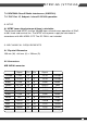
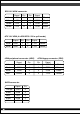
EPS 12V 8PIN connector Signal Pin Pin Signal Yellow +12V 5 1 COM Black Yellow +12V 6 2 COM Black Yellow +12V 7 3 COM Black Yellow +12V 8 4 COM Black ATX 12V 4PIN (4+4PIN EPS 12V in split mode) Signal Pin Pin Signal Black GND 1 3 +12V Yellow Black GND 2 4 +12V Yellow 4PIN peripheral connector (HDD) 4PIN floppy connector (FDD) Signal Pin Pin Signal Yellow +12V 1 1 +5VDC Red Black COM 2 2 COM Black Black COM 3 3 COM Black +5VDC 4 4 +12V Ye
ST85F-GS / ST75F-GS 8PIN PCI Express connector Signal Pin Pin Signal Yellow +12V 1 5 COM Black Yellow +12V 2 6 COM Black Yellow +12V 3 7 COM Black Black sense1 COM 4 8 COM Black 6PIN PCI Express connector Signal Pin Pin Signal Yellow +12V 1 4 COM Black Yellow +12V 2 5 COM Black Yellow +12V 3 6 COM Black
lssue date: June, 2013 NO.