
Owner manual

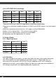

2.3 Output Ripple
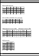
2.3.1 Ripple regulation
2.3.2 Definition
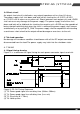
The ripple voltage of the outputs shall be measured at the pins of the output connector
when terminated in the load impedance specified in figure 1. Ripple and noise are
measured at the connectors with a 0.1uF ceramic capacitor and a 10uF electrolytic
capacitor to simulate system loading. Ripple shall be measured under any condition of
line voltage, output load, line frequency,operation temperature.
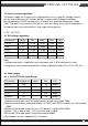
1.Maximum continuous total DC output power should not exceed 850W.
2.Maximum c.ontinuous combined load on +3.3VDC and +5VDC outputs shall not exceed
150W.
3.Maximum combined current for the +12V outputs shall be 70A(840W).
4.When +12V is load to 28A , -12V minimum load is 0.02A.
5.Peak total DC output power should not exceed 900W.
6.Peak power can be supported for 12 second.
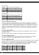
2.2.2: SST-ST85F-GS Load Range
Parameter
+3.3V
+5V
+12V
-12V
+5VSB
Min
0.5
0.3
1
0
0.1
Nom.
-
-
-
-
-
Max
22
25
70
0.3
3.5
Unit
Amps
Amps
Amps
Amps
Amps
Parameter
+3.3V
+5V
+12V
-12V
+5VSB
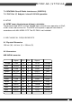
Ripple&Noise
50
50
120
120
50
Unit
mVp-p
mVp-p
mVp-p
mVp-p
mVp-p