
Integration Guide


REV070219
SimpliPhi Power, Inc. | 3100 Camino Del Sol | Oxnard, CA 93030, USA | (805) 640-6700 | info@simpliphipower.com | SimpliPhiPower.com
| 7 |
CAUTION: When PHI battery quantities change, the capacity & charge/discharge current settings
must to be reassessed. Failure to do so will void the Warranty.
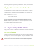
4.3 – MPPT Charge Controller Settings
Solar charge controllers must be used in DC coupled systems to regulate the power produced by the PV
array that is delivered to the batteries. Schneider Electric offers two different MPPT charge controllers,
both of which are compatible with PHI batteries:
1. Conext MPPT 80 600
2. Conext MPPT 60 150
The 80 600 model is somewhat unique in that allows for larger strings of PV modules to be easily
installed and connected to the PHI battery bank. Charge controller selection depends on the system size
and personal preference; The recommended setpoints for either Schneider Electric charge controller are
the same.
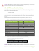
SimpliPhi Power recommends the 80% DoD settings in Table 2.0 below in order to maximize the
Warranty. Additional settings are outlined based on Warranty and desired cycle life.
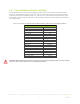
Table 2.0 - Settings for SimpliPhi PHI 3.8 kWh 24V & 48V Battery w/Schneider XW MPPT60/80
Conext MPPT60 / 80 Settings
10K Cycles
Warranty
5K Cycles
Warranty
3.5K Cycles
Warranty
Advanced Settings > Charger Settings
80% DoD
90% DoD
100% DoD
Batt Type
Custom
Custom Settings
Eqlz Supt
Disabled
Bulk Voltage
27.2V / 54.4V
27.2V / 54.4V
28V / 56V
Absorb Voltage
27.2V / 54.4V
27.2V / 54.4V
28V / 56V
Float Voltage
27V / 54V
Batt Temp Comp
0mV/C
Batt Capacity
2
151Ah (per PHI 3.8 24V) / 75Ah (per PHI 3.8 48V)
Max Charge Rate (C/2)
2,3
45A (per PHI 3.8 24V) / 37.5A (per PHI 3.8 48V)
Charge Cycle
3 Stage
ReCharge Volts
25.25V / 50.5V
Absorb Time
1 Hour
Default Batt Temp
Warm
Batt Voltage (Auto-detected)
24V / 48V
Aux Settings
Not Used
…
Default
Notes:
• 1. Maximum setting of 48V limited by some inverter firmware is below the recommended setting.
• 2. Per PHI 3.8 kWh 48V battery – These settings are calculated by multiplying the nominal value per-battery value times
the # of batteries. For other batteries, refer to the Warranty and Specification Sheet for the specific model. Refer to
Charge Controller Bank Sizing under the “Battery Bank Sizing” section.
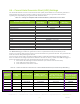
• 3. To calculate Max Charge Rate as a percentage, divide the calculated Max Bulk Current in Amps DC by the equipment’s
maximum potential charging current:
Bat QTY
PHI 3.8 / 24V
(45ADC)
1 x MPPT 80
(80ADC charger)
PHI 3.8 / 48V
(37.5ADC)
1 x MPPT 80
(80ADC charger)
2
90A
100%
75A
93%
• Levels are typical @ 25⁰C and may need adjusting at temperature extremes.
• When performing rapid deep charge/discharge cycles the battery should be allowed to "rest" 15 minutes in between.
• Always refer to the SimpliPhi Power Manual and Warranty for the specific PHI battery model.
CAUTION: When PHI battery quantities change, the capacity & charge/discharge current settings
must be reassessed. Failure to do so will void the Warranty.