INSTRUCTION MANUAL SIMRAD EQ44-2/EQ54-2 Echosounder 183-3453-102 06134.
About this manual The technical data, information and illustrations contained in this publication were to the best of our knowledge correct at the time of going to print. We reserve the right to change specifications, equipment, installation and maintenance instructions without notice as part of our policy of continuous development and improvement.
EQ44-2/EQ54-2 Echosounder Table of contents Chapter 1 Introduction and safety summary 1.1 Introduction and system familiarization .......................................1-1 1.2 Safety summary ........................................................................... 1-2 1.3 How to get started .........................................................................1-3 1.3.1 Dedicated function keys ............................................................... 1-4 1.3.2 Echosounder features .............
Table of contents EQ44-2/EQ54-2 Echosounder Chapter 6 ZOOM menu 6.1 ZOOM menu................................................................................. 6-1 Chapter 7 SHIFT menu 7.1 SHIFT menu ................................................................................. 7-1 Chapter 8 PILOT menu 8. PILOT menu ................................................................................. 8-1 8.1 Highway display ........................................................................... 8-1 8.1.
EQ44-2/EQ54-2 Echosounder Table of contents Chapter 12 Installation and service 12. Installation and service............................................................... 12-1 12.1 Installation notes ........................................................................ 12-1 12.2 Installation of EQ44-2 ................................................................ 12-3 12.3 Installation of EQ54-2 ................................................................ 12-5 12.4 Location for display unit ....
Table of contents EQ44-2/EQ54-2 Echosounder
Introduction and safety summary Chapter 1-1 1.1 Introduction and system familiarization Congratulations on your purchase of SIMRAD EQ44-2/EQ54-2 Echosounder and Fishfinder - a high performance echosounder in a unique slimline design with a bright 10” (EQ44-2) or 15” (EQ54-2) TFT color display. The EQ44-2/EQ54-2 is both an echosounder system with selectable frequency i.e.
Chapter 1-2 Introduction and safety summary 1.2 Safety summary Precaution: Do not open the equipment, only qualified persons should work inside the equipment. If the glass in the screen breaks, be careful not to get cut on the sharp edges of the glass pieces. ) The lifetime of the internal battery is minimum 5 years. If not exchanged before it goes flat, all data in the unit’s memory will be lost. We strongly recommend that you have the battery exchanged at your local Simrad workshop max.
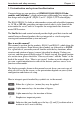
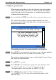
Introduction and safety summary Chapter 1-3 1.3 How to get started When starting up for the very first time, the first time after loading a new software or after a master reset: Make sure that all hardware installation and electrical connections are completed in accordance to the installation instructions. PWR Press and hold the [PWR] key until you have a picture on the screen The system will perform a software update and check for communication activity.
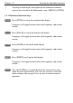
Chapter 1-4 ) Introduction and safety summary To call up an echo display will require that the connected transducer type has been selected in the Echosounder setup - [MENU],[8],[STND]. 1.3.1 Dedicated function keys STND Press [STND] to call up the standard echo display. Long press will toggle between echo, dual frequency, and custom screens. B-LCK Press [B-LCK] to call up the bottom lock display. Long press will toggle between echo, dual frequency, and custom screens.
Introduction and safety summary Chapter 1-5 1.3.2 Echosounder features A-scope - Press [ENT], [2] to toggle A-scope on/off. Echoes are displayed in a ‘bar-graph’ format. The strength of the actual echo is indicated by both width and color intensity. Change frequency - Press [ENT], [1] to toggle between e.g. 50 and 200 kHz. Gain - Adjust gain with the [GAIN-] and [GAIN+] keys to just below the point where you begin to see speckles of ‘noise’ on the screen.
Chapter 1-6 Introduction and safety summary
Fundamentals & initial start-up Chapter 2-1 2.1 Fundamentals of the display and page system The EQ44-2/EQ54-2 Echosounder has a multi-function screen and data presentation system with full screen and different types of split screens. The series of pages under the function keys (situated in the left column of the keypad) will in most situations be sufficient information for the operator. In split screens consisting of up to four displays, the active display is indicated by a solid red frame.
Chapter 2-2 Fundamentals & initial start-up Long press on the [PAGE] key will start a rotation of the four pages in intervals of 5 seconds (increase/decrease the time in [MENU], [8], [2]). Press any key to stop rotation. 2.1.1 Example of how to exchange a page in the PAGE system The four pages in the PAGE system are collected from the STND, B-LCK, ZOOM and SHIFT menus in the sequence of which the function keys appear on the keypad ie.
Fundamentals & initial start-up Chapter 2-3 Highlight a function e.g. Depth & temperature diagram in the MISC menu. WIN Press [WIN] several times to check the screen image (situated to the far right in the top line of the menu bar) which windows the function can be placed into ENT Press [ENT] to enter the highlighted function into the highlighted window ) If the function text in the menu is red, the display will not be available for the selected window. 2.
Chapter 2-4 Fundamentals & initial start-up B-LCK Shortcut to bottom lock displays. Long press will toggle between bottom lock display in full screen, Dual frequency, and two custom screens. ZOOM Shortcut to zoom display. Long press will toggle between zoom display in full screen, Dual frequency, and two custom screens. SHIFT Shortcut to shift display. Long press will toggle between shift display in full screen, Dual frequency, and two custom screens.
Fundamentals & initial start-up Chapter 2-5 2.3 Menu bar MENU Toggles the menu bar on/off To fit the complete menu bar across the screen, some of the menus have been abbreviated. However, the last selected menu will be highlighted, and if it’s an abbreviation of the menu, then the complete menu title is written above the menu bar. PILOT 1 STND WIN 2 3 B-LCK ZOOM 4 5 6 7 8 SHIFT PILOT ENG MISC SETUP 1 Highway 2 Position Having selected e.g.
Chapter 2-6 Fundamentals & initial start-up 2.
Fundamentals & initial start-up Chapter 2-7 2.5 Initial start-up When starting up for the very first time, the first time after loading a new software or after a master reset: Make sure that all hardware installation and electrical connections are completed in accordance to the installation instructions. PWR Press and hold the [PWR] key until you have a picture on the screen The system will perform a software update and check for communication activity.
Chapter 2-8 Fundamentals & initial start-up PWR Press [PWR] again to adjust the lighting in the screen and select day or night display etc., move around in display by means of the cursor key and change settings with +/- keys, and... ENT Confirm with [ENT] Customizing the EQXX to suit individual needs can be done as you go along i.e. choose a different color for the display background, text, menu, etc.
Fundamentals & initial start-up 2.8 Simrad WR20 Remote Commander (optional) Chapter 2-9 The WR20 is the first remote control that can both display and control the electronics on board when connected to the SimNet system. You can remotely command your NavStation with full MOB control from anywhere within a range of 100 m. You will have seamless control of pilot and navigation. You can make VHF calls from the WR20 and much, much more.
Chapter 2-10 Fundamentals & initial start-up
Echosounder operation Chapter 3-1 3. Echosounder operation The echosounder function of the EQXX determines the distance between its transducer and underwater objects such as fish, lake bottom or sea bed. It does this by utilizing the fact that an ultrasonic wave transmitted through water travels at a nearly constant speed of 1500 meters (4800 feet) per second. When a sound wave strikes an underwater object such as fish or sea bottom, part of the sound wave is reflected back toward the source.
Chapter 3-2 Echosounder operation 3.1 Parts of an echosounder An echosounder is composed of a display screen, processor, and transmitter/ receiver unit which in the case of the EQXX are housed in one unit. Connected to this unit by a shielded cable is the transducer, which is mounted horizontally on the bottom of the hull or on the transom. The display screen presents in graphic and numerical form the information the processor is receiving and accumulating from the transducer.
Echosounder operation Chapter 3-3 3.2 How the echosounder works When the EQXX is turned on, a transmitter begins to send electrical pulses to the transducer. The ceramic resonator in the transducer has a special property which enables it to change dimensions slightly when a varying voltage is applied. The voltage is thus converted to mechanical vibrations (sound waves) which are then transmitted down through the water. See Fig. 1. Fig. 1 Transmitted ‘ping’ from the transmitter/receiver.
Chapter 3-4 Echosounder operation 3.3 Transducer beam width The transducer mounted to the hull of your vessel serves as both a ‘speaker’ when transmitting, and as a ‘microphone’ when the echosounder is receiving. Similar to the way a flashlight focuses light, most of the sound from your transducer is focused downwards with a smaller amount going out to the sides. The amount of focusing of the sound beam is expressed as a ‘beam width’.
Echosounder operation Chapter 3-5 3.4 Effects of the vessel’s speed The presentation of fish on the EQXX depends directly on the vessel’s speed, as well as on the depth of the fish. When the vessel is at rest, the echo traces will appear stretched and flattened. As the vessel’s speed becomes greater, the echo traces will become shorter and more arched. The reason for this change in appearance is that as the vessel speed increases, fewer number of sound ‘pings’ strike each fish.
Chapter 3-6 Echosounder operation
STND menu Chapter 4-1 4.1 STND menu 1 STND 1 50kHz (38kHz) 2 200kHz 3 Dual frequency 4 Custom screen 1 5 Custom screen 2 Low and high frequency echosounder display can be set up separately. The low frequency display will show deep water bottom contours, and the high frequency display will show the mid-water section with trawl targets or bait fish in a higher resolution. The Dual frequency display will provide both the 50kHz and the 200kHz echo displays in one screen.
Chapter 4-2 STND STND menu From any display: Long press on the [STND] key will toggle between: 38/50kHz or 200kHz full screen Dual frequency Custom screen 1+2 4.3 Standard echo display This is the basic presentation mode (standard display) for observing fish schools and sea bed. Some surface noise may appear just below the transmission line. Transmission line. Time scale. Depth range is adjustable with +/- keys or the Quick-range keys 1-9. Press key 0 to return to Auto range.
STND menu 1-9 Select range in 9 steps +/- Adjust range with the + and - keys 0 Chapter 4-3 Activate Auto range Press cursor left/right to adjust gain ADJ Direct access to Setup display related to active echo display 50kHz or 200kHz - (see section 4.7) Use the cursor to go to the function you wish to change the value for +/- Toggle between available values ENT Confirm changes, or... MENU Abandon changes and exit Setup display 4.
Chapter 4-4 STND menu 4.5 Echo quick menu A number of echo features can easily be accessed from the Echo quick menu. ENT From active echo display: Call up the Echo quick menu with access to the following features: Echo quick menu 1 Change frequency 2 Hide A-scope STND Transmit power off MENU Exit 1 Change frequency will toggle between 38, 50 or 200kHz displays (Airmar transducers) to suit the task. 200 kHz is for general purpose and offers optimum discrimination and a narrow transmitter beam.
STND menu Chapter 4-5 4.7 Presentation setup The general Echosounder setup e.g. Selecting transducer, Alarm settings, Demo mode etc. is placed in the SETUP menu (section 10.1). The echo setup in this chapter are the most common settings for adjusting the presentation of the high or low frequency echo picture, and can be accessed by a single keystroke.
Chapter 4-6 STND menu Range – refers to the distance shown from the top to the bottom of the display screen. Selecting Auto range will cause the EQXX to change the basic range setting(s) to keep the displayed bottom in the lower half of the display. For instance, as your boat moves into deeper waters, the system will automatically switch to a deeper range, always keeping the displayed bottom in the lower half of the display. Manual range allows the operator to set the range displayed on the screen.
STND menu Chapter 4-7 Ping to ping filter – can be set to either on or off. With the filter “off”, then each received echo will be reflected on the screen. Whereas with the filter “ON”, the system will compare every two echoes received and only reflect on the screen what is received from both echoes, which will give a more uncluttered recording. Signal threshold – can be set to ON to eliminate the appearance of unwanted noise.
Chapter 4-8 STND menu Scroll speed – is the ping rate and movement of the presentation of echoes on the screen, moving from right to left. It is adjustable (Low, Medium, High, Max, Freeze), to allow the user to show a longer “history” on the display screen, if desired.
B-LCK menu Chapter 5-1 5.1 B-LCK menu 2 B-LCK 1 50kHz (38kHz) 2 200kHz 3 Dual frequency 4 Custom screen 1 5 Custom screen 2 Low and high frequency echosounder display can be set up separately. The low frequency display will show deep water bottom contours, and the high frequency display will show the mid-water section with trawl targets or bait fish in a higher resolution. The Dual frequency display will provide both the 50kHz and the 200kHz echo displays in one screen.
Chapter 5-2 B-LCK menu The advanced bottom lock and expansion feature ensures a reliable depth readout and provides a compressed standard display in the upper part of the screen. The bottom area can be magnified for better separation of echoes. The actual size of the expansion window can be adjusted in the presentation setup. Transmission line. Time scale. Depth range is adjustable with +/- keys or the Quick-range keys 1-9. Press key 0 to return to Auto range.
ZOOM menu Chapter 6-1 6.1 ZOOM menu 3 ZOOM 1 50kHz (38kHz) 2 200kHz 3 Dual frequency 4 Custom screen 1 5 Custom screen 2 Low and high frequency echosounder display can be set up separately. The low frequency display will show deep water bottom contours, and the high frequency display will show the mid-water section with trawl targets or bait fish in a higher resolution. The Dual frequency display will provide both the 50kHz and the 200kHz echo displays in one screen.
Chapter 6-2 ZOOM menu This feature will provide an expanded view of the area near the *VRM line which will give a better separation of echoes. The actual size of the expansion window can be adjusted in the presentation setup. *) See section 4.4 Variable range marker. Transmission line. Time scale. Depth range is adjustable with +/- keys or the Quick-range keys 1-9. Press key 0 to return to Auto range.
SHIFT menu Chapter 7-1 7.1 SHIFT menu 4 SHIFT 1 50kHz (38kHz) 2 200kHz 3 Dual frequency 4 Custom screen 1 5 Custom screen 2 Low and high frequency echosounder display can be set up separately. The low frequency display will show deep water bottom contours, and the high frequency display will show the mid-water section with trawl targets or bait fish in a higher resolution. The Dual frequency display will provide both the 50kHz and the 200kHz echo displays in one screen.
Chapter 7-2 SHIFT menu This feature can be applied when operating in deep waters. The expansion window can automatically follow a changing bottom or be set manually by means of the numeric keys 1-9, and then use the +/- keys or cursor to move the window up/down. Press the [0] key for automatic bottom tracking. Transmission line. Time scale. Press cursor left/right to adjust gain ADJ Direct access to presentation setup related to active echo display 50kHz or 200kHz - (see section 4.
PILOT menu Chapter 8-1 8. PILOT menu 5 PILOT 1 Highway 2 Position 8.1 Highway display To present any information in the EQXX highway display will require that a navigator is connected via SimNet or the NMEA input port - refer to section 12.5 Electrical connections. ) The connected navigator must be in navigation mode, which could be Cursor, Waypoint, Route or Track navigation - see next page. 8.1.1 Navigation setup MENU 5,1 Call up the menu bar, and...
Chapter 8-2 ENT PILOT menu Return to Highway display Highway display (with active navigation mode) d e c e Nautical miles indication (0.10nm and 0.20nm) on horizontal lines indicates how many nautical miles there are from ship’s position to the horizontal line. C: Course over ground X: Cross-track-error S: Speed over ground B: Bearing to approaching WP D: Distance to waypoint V: Speed towards WP (velocity) Bottom line indicates name/number of approaching waypoint or routepoint.
PILOT menu Chapter 8-3 8.2 Position display ) To present a position will require that the echosounder is connected to a navigator (GPS position sensor). MENU 5,2 Call up the menu bar, and... load Position display Trip log 1 and 2. Position in three decimals in minutes. Water speed/speed over ground. External POS Course, magnetic or true.
Chapter 8-4 CLR Reset log 0-9 Key in new values, or... +/- Toggle between available values ENT Confirm editing and return to the Position display PILOT menu Log - reset log or insert alternative start figure by altering the value in the “Log 1” and/or “Log 2” line. Press [CLR] to reset the figure, and press the numeric keys 0-9 to alter the figure. Additional data - can be set to DEPTH or COMPASS. DEPTH will be shown from built-in echosounder. COMPASS will show heading from connected sensor.
Engine monitoring Chapter 9-1 9. Engine menu 5 ENG 1 Engine status - see section 9.1 2 Fuel and transmission - see section 9.2 3 Battery status - see section 9.3 4 2nd Engine status - see section 9.4 5 2nd Fuel and transmission - see section 9.4 6 2nd Battery status - see section 9.4 This graphical engine monitoring system is available for engines outputting data via NMEA2000® or an appropriate interface device supporting NMEA2000®.
Chapter 9-2 Engine monitoring For dual engines, the system provides ‘dual bar analog instruments’ to give a precise overview of the rpm synchronization and to make direct comparison of data between the two engines. The engine monitoring system provides analog graphical gauges and digital (numerical readings) data for up to four engines - see display examples further on in this chapter.
Engine monitoring Chapter 9-3 9.1 Engine status MENU 6,1 Call up the menu bar, and... load the Engine status display Forward Reverse (N = Neutral) The numbers at the bottom represents Engine 1 to the left and Engine 2 to the right in each column. The Engine status display will provide data from 1 or 2 engines. If there are more than 2 engines on board (and connected to the system), a second Engine status display is available by pressing: [MENU], [6], [4].
Chapter 9-4 Engine monitoring Engine RPM limit, default is 4200 RPM. To control the limit manually, you can insert a new limit by means of the numerical keys. When the limit is exceeded, the green fill color will turn red. Oil pressure range, default is 100 Psi. Use numerical keys to enter new range. Can be shown in Psi (10-125 Psi) or Pascal (69-862 kPa). Turbo pressure range, default is 50 Psi. Use numerical keys to enter new range. Can be shown in Psi (10-125 Psi) or Pascal (69-862 kPa).
Engine monitoring Chapter 9-5 In the top part of this display you have read-outs for Engine 1 to the left and Engine 2 to the right and a total for both in the middle. The second line in the middle i.e. ‘17.0 L/nm’ - liter per nautical mile, is calculated by the NavStation. The read-out can be presented in L/nm, L/km, L/mi, G/nm, G/km, G/mi. The unit can be selected in [MENU], [8], [1], see section 10.5. The numbers at the bottom represents Engine 1 to the left and Engine 2 to the right in each column.
Chapter 9-6 Engine monitoring Right engine source - use +/- to toggle between connected engines. Transmission oil temperature range, default is 120 degrees Celcius. Use numerical keys to enter new range. Can be shown in Celcius (50°C to 300°C) or Fahrenheit (122°F to 572°F). Transmission oil pressure range, default is 100 Psi. Use numerical keys to enter new range. Can be shown in Psi (10-500 Psi) or Pascal (69-3447 kPa). Fuel pressure range, default is 100 Psi. Use numerical keys to enter new range.
Engine monitoring Chapter 9-7 Battery status setup Left battery source: Right battery source: ENGINE 1 ∆ ENGINE 2 BATTERY 1 BATTERY 2 Left alternator volt.range:10-15 Volt Right alternat. volt.range:10-15 Volt Left battery voltage range:10-15 Volt Left battery current range: 60 Amp Right battery volt.range: 10-15 Volt Right batt. current range: 60 Amp MENU Exit ∆ Left engine source: Right engine source: Accept ENT Left engine source - use +/- to toggle between connected engines.
Chapter 9-8 Engine monitoring 9.4 Second set of engine monitoring displays The menu points 4, 5 and 6 are a second set of displays, which only will be visible if the system detected more than two engines on board. MENU 6,4 MENU 6,5 MENU 6,6 Call up the menu bar, and... load the 2nd Engine status display - refer to section 9.1. Call up the menu bar, and... load the 2nd Fuel and transmission display - refer to section 9.2. Call up the menu bar, and...
Miscellaneous menu Chapter 10-1 10. Miscellaneous menu 7 MISC 1 Decca lanes 2 Loran C 3 Depth & temperature diagram 10.1 Decca lanes To change the position readouts to decca mode, see section 11.2 under Pilot/Position setup, where ‘Display position as’ can be toggled to ‘Decca’. MENU 7,1 Call up the menu bar, and... load decca chain display ADJ Open for change +/- Leaf through the available chains - see next page.
Chapter 10-2 Miscellaneous menu List of decca chains: 00 01 02 03 04 05 06 07 08 09 10 11 12 13 14 15 16 17 18 19 20 21 22 23 S Baltic Vestlandet SW British North Humber Holland British Lofoten, Norway German N Baltic NW Spanish Trondelag (N) English N Bothnian S Spanish N Scottish Finland Danish Irish Finnmarken French S Bothnian Hebridean Frisian Helgeland 0A 0E 1B 2A 2E 3B 3E 3F 4B 4C 4E 5B 5F 6A 6C 6E 7B 7D 7E 8B 8C 8E 9B 9E 24 25 26 27 28 29 30 31 32 33 34 35 36 37 38 39 40 41 42 43 44 45 46 Skag
Miscellaneous menu Chapter 10-3 10.2 Loran C To change the position readouts to Loran C mode, see section 11.2 under Pilot/Position setup, where ‘Display position as’ can be toggled to ‘Loran C’. MENU 7,2 Call up the menu bar, and... load Loran C chain display ADJ Open for change +/- Leaf through the available chains - see listing next page. If required, go to the slaves, and... +/- Toggle between available slaves (not all chains have more than one slave) 0-9 ...
Chapter 10-4 Miscellaneous menu List of Loran C chains: Central Pacific Gulf of Alaska Southeast U.S. Great Lakes Northeast U.S. Canadian West Coast Canadian East Coast Labrador Sea West Coast U.S. North Pacific 4990 7960 7980 8970 9960 5990 5930 7930 9940 9990 Commando Lion North West Pacific Norwegian Sea Mediterranean Sea Icelandic Saudi Arabia South Saudi Arabia North Eastern U.S.S.R. Western U.S.S.R.
Miscellaneous menu Chapter 10-5 10.3 Depth & temperature diagram MENU 7,3 Call up the menu bar, and... activate Depth & temperature diagram Present water temperature and depth. Depth over time or distance. Temperature over time or distance. ADJ Call Setup for Depth Setup for Depth: Scale for depth: 0 -> 100 m Color for depth: Scale for temperature: Color for temperature: Interval of screen: Time interval: Go to the function you wish to change 0 -> 20 °C TIME 5 MIN.
Chapter 10-6 0-9 +/- Key in new figures, or... change settings ENT Confirm changes Miscellaneous menu Scale for depth - there are six depth scales to choose from, ranging from 0 -> 10m to 0 -> 3000m. Toggle between values with +/- keys. Color - for depth and temperature can be changed. Toggle between available colors by means of the +/- keys. Scale for temperature - can be set to 0 -> 10°, 0 -> 20°, 0 -> 30°, 10 -> 20°, and -10 -> 10°.
SETUP menu Chapter 11-1 11. Setup menu 8 SETUP STND Echosounder setup - see section 11.1 1 Pilot/Position setup 2 Speed alarm, units & language - see section 11.3 3 Interface setup - see section 11.4 4 Palette setup - see section 11.5 5 Factory settings - see section 11.6 6 QuickGuide - see section 11.7 - see section 11.2 11.1 Echosounder setup The Echosounder setup display mainly consist of general settings, but also applies to a specific frequency where stated.
Chapter 11-2 SETUP menu Echosounder setup: Select transducers: Transducer 1: Transducer 2: TYPE BEAM ANGLE NONE NONE PORT ECHO1 ECHO2 DEPTH Keel depth below surface: 00.0 m Display: DEPTH BELOW KEEL Data on NMEA-out from: NONE Alarm for fish: Strength: 065% OFF Depth DS fish: min: 0005 m max: 0030 m Depth DK alarm min.: 0005.0 m OFF Depth DK alarm max.: 0030.0 m OFF Water profile: SALT Velocity of sound in water: 1470m/s Time/distance scale: ON Restart of AUTO pulse/power: 20 sec.
SETUP menu Chapter 11-3 Depth DS fish - define a specific area below the water surface of minimum and maximum depth for the fish alarm. Depth DK alarm min. and max. - set up a depth limit alarm for depth below keel. Water profile - choose between SALT and FRESH water. The setting will reflect on the: Velocity of sound in water: SALT = 1470 meters per second and FRESH = 1430 meters per second as standard.
Chapter 11-4 SETUP menu 11.2 Pilot / Position setup MENU 8,1 Call up the menu bar, and... load Pilot/Position setup display Pilot/Pos setup: Display position as: Display speed as: Course and bearing as: Time: 13:43:56 Date: MENU Exit LAT/LON STW MAGNETIC 15-01-2006 Accept ENT Go to the function you wish to change 0-9 +/- Key in new values, or...
SETUP menu Chapter 11-5 11.3 Speed alarm, units & language MENU 8,2 Call up the menu bar, and... load Speed alarm, units & language display Setup for speed: Speed alarm maximum: Speed alarm minimum: 000.0kn 000.0kn OFF OFF Setup for units: Depth/altitude in: METERS NAUTICAL MILES KNOTS DEGREE CELCIUS PSI LITER EQ44/54 4.00 Distance in: Speed in: Temperature in: Pressure in: Volume in: Software version: AT44 version: HW rev.: 0,SW:- 2.00 PAGE rotation interval: Display text in: MENU Exit 05 sec.
Chapter 11-6 SETUP menu Distance in - can be calculated in nautical miles (nm), kilometers (km) or statute miles (mi). Speed in - can be shown in knots (kn), kilometers/hour (kh) or miles/hour (mh). Pressure in - can be shown in Psi or Pascal (kPa). Volume in - can be shown in liter or gallon. Software version - indicates which software version is installed in the unit. AT44 version - indicates if an AT44 SimNet converter is connected and which revision hardware and software is implemented.
SETUP menu Chapter 11-7 11.4 Interface setup EQ44-2/EQ54-2 has two NMEA in/out ports: 1. NMEA1 is a standard NMEA0183 port. 2. NMEA2 is used for connection to SimNet or NMEA2000 via AT44 Active Tee or for standard NMEA interfacing. Plug-and-play: SimNet offers easy and uncomplicated interfacing with a unique cable and plug solution and automatic system setup. SimNet is the optimum solution for integrating SimNet products and other products with NMEA 2000. Group selection or stand-alone: Main products, e.
Chapter 11-8 SETUP menu (products) operating on the SimNet bus. See below example: Additional + data + + No addi- + tional data GAIN- 1: 2: 3: 4: : MENU Nodes Position Navigation GAIN+ ► Simrad EQ44 Simrad CA34-3 Airmar EQS Simrad RC35 NMEA-PORT ,Sn:3DD0BD ,Sn:5C514D ,Sn:000000 ,Sn:000035 Exit Automatically assigned network address ∆ Internal serial number ∆ ◄ Accept ENT Product model numbers (top line is own unit); -1, -2, -3 etc. indicates multi sources.
SETUP menu Chapter 11-9 Group selection can be set to: SIMRAD - auto-selected SimNet units from the Simrad group. STAND-ALONE - manually selected data source and third party units. Source: - depending on which products (sources) are connected, the legend will indicate: ‘none available’, ‘one available’, ‘multiple available’ or ‘owned, data type locked’.
Chapter 11-10 Go to Water interface - step back with [GAIN-] ◄ GAIN- Navigation Water Compass Wind Al GAIN+ ► Water depth input: INTERNAL ONLY ∆ Group selection: SIMRAD Source (multiple available): Simrad EQ44 ,Sn:3DD0BD Water temperature input: Group selection: SIMRAD Source (one available): Airmar EQS ,Sn:000000 Water temperature offset: +0.0°C Water speed input: Group selection: Source (one available): Airmar EQS LOG speed cal.
SETUP menu GAIN+ Chapter 11-11 Go to Compass interface - step back with [GAIN-] ◄ GAIN- Navigation Water Compass Input: Group selection: Source (none available): GAIN+ SIMRAD ► ∆ NONE ∆ MENU GAIN+ Exit Accept ENT Go to Engine interface - step back with [GAIN-] ◄ GAIN- Water Compass Engine Ala GAIN+ ► ∆ PORT ,Sn:06952E-0 Engine 2: STARBORD Teleflex PIN-1 ,Sn:060000-1 Battery 1: Battery 1 Teleflex PIN ,Sn:06952E-0 Battery 2: Battery 2 Teleflex PIN-1 ,Sn:060000-1 Teleflex PIN Engine/batte
Chapter 11-12 SETUP menu Stand-by level can either be: LOW = 0 volt or HIGH = 5 volt. GAIN+ Go to SimNet diagnostic interface - step back with [GAIN-] ◄ GAIN- Alarm SimNet diagnostic S GAIN+ ► CRC checksum error counter: 0 ∆ Receive que full: 0 Transmit que full: 0 ∆ MENU Exit Accept ENT CRC checksum error counter - if the figure is not 0 it could be due to a number of things and not necessarily that there is a system error.
SETUP menu GAIN+ Chapter 11-13 Go to the next and last interface: Identification - step back with [GAIN-] ◄ GAIN- 83 output Identification Unit description: GAIN+ ► ∆ ECHO SOUNDER Device instance 000 System instance 000 ∆ MENU Exit Accept ENT Unit description - can be customized to read e.g. BACK-UP UNIT. Maximum number of characters is 16. The identification name can be seen in the Nodes interface - refer to the beginning of this section. ENT MENU Confirm editing, or...
Chapter 11-14 SETUP menu Description of navigation input sentences APB Autopilot sentence “B”. RMB Recommended minimum navigation information. XTE Cross-Track-Error, measured. 11.4.
SETUP menu Chapter 11-15 11.5 Palette setup Quick change of preset color palettes via the [PWR] key. MENU 8,4 Call up the menu bar, and... load the Palette setup Palette 1 to 4 are preset to 1:Bright (sunshine), 2:Day (normal daylight), 3:Dusk and 4:Night settings. These four setups are not adjustable. Palette 9:Multi is preset with multi colors. Palette 5 to 8 can be customized to suit individual needs and wishes. If you wish to make your own special palette setup in e.g.
Chapter 11-16 SETUP menu Alphanumeric names: First select the key with the desired letter, then you can either repeat the keystrokes, which will toggle between e.g. A,B,C,1, or once you have selected one letter you can go back and forth in the alphabet by means of the +/- keys. Use the cursor key to go to next space or to go back one space if you make a mistake. Depending on the selected language, the 0 (zero) key will hold special characters e.g.
SETUP menu MENU Chapter 11-17 If not absolutely sure, press [MENU] to exit function without having made any changes Activating ‘Return to all factory presets’ will erase all user-made settings and restore the basic default settings from the factory. The unit will restart with ‘Automatic input source setup’ as described in section 2.5 Initial start-up.
Chapter 11-18 SETUP menu 11.7 QuickGuide A description of the key functions and general guidance is available in a QuickGuide, which can be accessed either at start-up display - press [PAGE], or via the menu: MENU 8,6 Call up the menu bar, and...
Installation and service Chapter 12-1 12. Installation and service 12.1 Installation notes For a number of reasons, all user-related decisions, setups, etc. should be noted in these two pages as they occur. This information may be helpful if your unit has been updated with new software, reset or in for service.
Chapter 12-2 Other important settings: Installation and service
Installation and service Chapter 12-3 12.2 Installation of EQ44-2 245 mm (9.6”) 220 mm (8.8”) The unit can be flat or bracket mounted - overhead, bulkhead or console. 343 mm (13.5”) 42 (1.7”) 365 mm (14.4”) 110 mm (4.3”) 75 mm (3.0”) Console mounting. Overhead mounting. Bulkhead mounting.
Chapter 12-4 Installation and service Flush mounting of EQ44-2 Removable corner for flush mounting. Minimum clearance incl. cables: 11 cm. 192 mm (7.6”) 202 mm (7.9”) 208 mm (8.2”) 220 mm (8.7”) Refer to included template for instructions on flush mounting. 337 mm (13.3”) 347 mm (13.7”) 353 mm (13.9”) 365 mm (14.
Installation and service Chapter 12-5 12.3 Installation of EQ54-2 42 (1.7”) 343 mm (13.5”) 460 mm (18.1”) 195 mm (7.7”) Console mounting. Bulkhead mounting. 339.2 mm (13.4”) 330 mm (13”) The unit can be flat or bracket mounted. Overhead and bulkhead mounting is only possible if using a distance piece.
Chapter 12-6 Installation and service Flush mounting of EQ54-2 Removable corner for flush mounting. Minimum clearance incl. cables: 13 cm. 297.9 mm (11.7”) 307.9 mm (12.1”) 318 mm (12.5”) 330 mm (13”) Refer to included template for instructions on flush mounting. 427.9 mm (16.8”) 437.9 mm (17.2”) 448 mm (17.6”) 460 mm (18.
Installation and service 12.4 Location for display unit Chapter 12-7 Determine which place is the most suitable and convenient for navigation and general operation after considering the following conditions: - you can see the ship’s bow when you raise or lower your eyes from the display. - there is limited exposure to direct sunlight to avoid overheating - see environment temperature limits in 12.10 Specifications. - there is good ventilation and minimum vibration.
Chapter 12-8 Installation and service 12.
Installation and service Chapter 12-9 1: NC 2: NC 3: Black 4: Red w/fuse
Chapter 12-10 Installation and service 12.5.1 Power supply connections The internal voltage regulator will allow the EQXX to operate normally within the power supply voltage range from 10 to 32 V DC. The EQXX is connected to external power (battery) by means of the supplied power cable, which is approximately 2 meters long and is not extendable.
Installation and service Chapter 12-11 Transducer connections: Internal connections Transceiver Transceiver 1 2 50/200kHz 38/200kHz ECHO1 ECHO2 Combi transducer 38 and 200, or 50 and 200kHz Single frequency 50 or 200kHz Single frequency 38 or 200kHz Two frequency 50/200kHz ! Warning! Transducers containing speed log sensor e.g. Airmar B744V must never be connected to the port “ECHO2”. To avoid accidental connection, “ECHO2” is sealed with a small silicone plug, which of course is removable so e.g.
Chapter 12-12 Installation and service 12.5.4 Interface connection The 44 and 54 series feature three possibilities for interconnection and data sharing: 1. SimNet, which is recommended for control and data sharing between Simrad SimNet products. 2. NMEA2000, SimNet products will interface and share data with NMEA2000 based products. 3. NMEA0183, which has been the common standard for marine electronics.
Installation and service Chapter 12-13 SimNet power and termination The following simple rules should be observed when installing SimNet: • SimNet must be powered with 12 VDC and connected to the battery via circuit breaker and 5 amp fuse. • Do not connect the SimNet power cable to the same terminals as the Autopilot Computer, Radar, thruster or other high current products.
Chapter 12-14 Installation and service 12.6 Basic transducer and cable information For optimum performance of the Echosounder, the Simrad combi transducers C38/200 and C50/200 are recommended. These transducers also include a water temperature sensor. A variety of alternative medium-range transducers is available for vessels mainly operating in shallow waters and/or where the size of the transducer is critical.
Installation and service Chapter 12-15 12.6.1 Transducers (option) Simrad Combi-transducers C50/200 or C38/200 124.5 92 310 135 400 Combi C50/200 or C38/200 combines two transducers and a temperature sensor in one housing. It has a streamlined shape, designed for mounting onto the hull.
Chapter 12-16 Airmar P319 Installation and service Thru-hull mount Frequency: 50/200 kHz Beamwidth: 45° / 15° Cable length: 10m (32’) Depth information. Reference no. 179-0401-002 (P319) Housing: Reinforced plastic Recommended for fiberglass and metal hulls. Do not use in wooden hulls! Reference no. 179-0401-003 (B117) Housing: Bronze Recommended for fiberglass and wooden hulls.
Installation and service Chapter 12-17 Airmar SS505 Thru-hul stem mount Accomodates hull thickness: Min. no fairing 6 mm (1/4”), Max. with fairing 83 mm (3 1/4”) Frequency: 50/200 kHz Beamwidth: 45° / 15° Cable length: 10m (32’) Depth information. Ref.no. 179-0401-004 (B45) Housing: Bronze Recommended for fiberglass or wooden hulls only. Ref.no. 179-0401-008 (SS505) Housing: Stainless steel Recommended for any hull material. Ref.no.
Chapter 12-18 Installation and service Airmar B744V Thru-hull triducer Frequency: 50/200 kHz Beamwidth: 45° / 15° Cable length: 10m (32’) Speed, temperature + depth information. Ref.no. 179-0401-009 (B744V) Housing: Bronze Recommended for fiberglass and wooden hulls. Do not connect to ECHO2 port. 12.6.
Installation and service Chapter 12-19 Due to the varying design of ship’s hulls and different operating speeds, there can be great variation in the amount of air bubbles which are carried beneath the hull. These bubbles tend to be carried close to the hull as they pass aft.
Chapter 12-20 Installation and service 12.7 Preventive maintenance Surface cleaning – to keep the EQXX cabinet and display screen clean, wipe the surfaces with a clean damp cloth. For heavier cleaning, use a clean, damp cloth which has been dipped in a solution of a mild dish detergent and water. Wring out firmly before wiping the unit. Never use cleaning solutions containing spirit, alcohol, gasoline or oils. Electrical connections – periodically check the electrical connections.
Installation and service Chapter 12-21 12.9 Troubleshooting For all fault finding, first check that the supply voltage is between 10-32 VDC Symptom No picture on display screen Check Remedy Check that the unit is turned on Check fuse in power cable fuse holder Press the [PWR] key on keypad Replace fuse. Use only type T6.
Chapter 12-22 Symptom Installation and service Check Remedy Unstable or no data from SimNet. Check connection of SimNet cables. Check for stable 12 Volt supply. Check termination is correct. All data is deleted after turning off the unit and turning it back on Check battery lifetime. Expected lifetime is min. 5 years Use minimum one termination e.g. the power cable with red disc. Perform SimNet system reset, see section 11.6. Internal battery must be replaced by authorized dealer 12.
Installation and service Chapter 12-23 Echosounder section Frequencies: 38, 50 and 200 kHz, selectable Output power: Variable up to 1kW RMS per channel Impedance: 75 ohms Display ranges: 5 to 2000 m (38/50kHz), 5 to 400kHz) in steps (manual) and auto mode.
Chapter 12-24 P66: P319: Installation and service 600W plastic transom mount triducer, depth, speed and temperature, 45° and 15° beam. 600W plastic thru-hull transducer, 45° and 15° beam. ST850: Speed and temperature only. Cables and accessories included Power cable, 2 m, 4-pin female connector incl. fuse T6.
Glossary of terms Appendix A-1 Alarms – can be set to sound a “beep” if the echosounder detects a target above (shallower than) a minimum alarm depth or below (deeper than) a maximum alarm depth. The EQXX allows you to set the alarm depths and to enable or disable both the minimum and maximum depth alarms. A-scope – a method of displaying the echosounder information.
Appendix A-2 Glossary of terms MENU – the selection of main menus will be shown in the upper part of the screen. Leaf through the menus by means of the cursor key and the [ENT] key, or use the numerical keys to activate one of the menus. NMEA – National Marine Electronics Association. The NMEA is an organization of manufacturers of marine electronics equipment. They have adopted the NMEA0183 as a standard for communications between various types of marine electronic equipment.
EQ44-2/EQ54-2 Echosounder Index Agents end of manual Alarms, - depth 11-2,A-1 - fish 11-2 - speed 11-5 - XTE 8-1,A-2 Alphanumeric names 11-16 B-LCK menu CE Declaration Configuration Contrast & light Course over ground - magnetic or true 5-1 end of manual A-1 2-8 8-2 8-3 Daylight display 11-15 Decca lanes 10-1 - list of decca chains 10-2 Depth in position display 8-3 Depth & temperature diagram 10-5 Display color 11-15 Echo quick menu 4-4 Echosounder features 1-5 - A-scope 4-5,A-1 - background color 11-1
Index EQ44-2/EQ54-2 Echosounder Installation - continued, - EQ44-2 - EQ54-2 - determining the position for the transducer - location for display unit - notes - sources of noise - transducers (optional) Interface setup, alarm output Interface setup - description of sentences - return to SimNet/NMEA presets Introduction Key functions -dedicated function keys Key symbols in manual Language Light & contrast Local time and date Log - reset - speed calibration Loran C - list of Loran C chains Maintenance Master
EQ44-2/EQ54-2 Echosounder Index
EU Declaration of Conformity I, the undersigned, hereby declare that the following equipment complies with the relevant essential requirements in the EMC Directive. EMC Directive 89/336/EEC of May 3rd, 1989 Conformity assessment Employed harmonised standard Equipment category Navigational equipment intended for world-wide use aboard non-SOLAS vessels Model(s) Simrad EQ44-2 and EQ54-2 Echosounder EN60945.
Warranty SIMRAD warrants that every product shall be free of defects in material and workmanship as specified below: CATEGORY “A”: •Autopilots •Radars •Instruments •Navigators •Radiotelephones •Plotters •Gyro compasses incl. sensitive elements •Sonars •Echosounders •Trawl Instrumentation •SatCom •SatTV. These products are warranted for a period of 24 months on parts and 12 months on labor from date of purchase, except for category B items. Consumable parts such as lamps, fuses, batteries, bearings, etc.
___________________________________________ HOME PORT _____________________________________________ ADDRESS AUTHORIZED INSTALLER/DEALER STAMP ___________________________________________ __________________________ DATE OF INSTALLATION ______________________ DATE OF PURCHASE ____________________________________ ____________________________________ ________________________________________________________________________ EQUIPMENT __________________________________________________________ TYPE SIMR
_____________________________________________ ________________________________________ ________________________________________ (DEALER’S SIGNATURE) DATE OF INSTALLATION DATE OF PURCHASE (CUSTOMER’S SIGNATURE) ________________________________________ ________________________________________ ____________________________________ ____________________________________ ________________________________________________________________________ EQUIPMENT ___________________________________________________
_________________________________________________________________________ _________________________________________________________________________ _________________________________________________________________________ _________________________________________________________________________ NATIONAL SIMRAD DISTRIBUTOR: STAMP HERE