MANUAL SIMRAD AP35 Autopilot 22083083K Sw.
Instruction Manual Instruction Manual This manual is intended as a reference guide for operating and correctly installing the Simrad AP35 autopilot. Great care has been paid to simplify operation and set-up of the AP35, however, an autopilot is a complex electronic system. It is affected by sea conditions, speed of the vessel, hull shape and size.
Simrad AP35 Autopilot Document revisions Rev F G H I J K Date 21.12.01 04.06.02 08.10.03 22.11.04 20.03.06 19.01.07 Written by NG NG NG NG NG Checked by IK IK IK Approved by TR TR TR VP IK Document history Rev. – Original Issue F Following corrections: STBY button section 2.3. Conductor color on figure 4-19. HDM message on page 83. Added FU35 under Comm. Failure alarm page 95. G Minor corrections in text on page 58, 83 and 85. Distributor list updated. H Updated according to software version V1R4.
Instruction Manual Contents 1 GENERAL INFORMATION ............................................................................................... 7 1.1 Introduction .............................................................................................................. 7 1.2 How to use this manual............................................................................................. 7 1.3 System components .........................................................................................
Simrad AP35 Autopilot 3.4 3.5 3.6 3.7 3.8 3.9 3.10 3.11 3.12 3.13 3.14 3.15 RFC35 Fluxgate compass ....................................................................................... 30 RC25 Rate Compass ............................................................................................... 31 CDI35 Course Detector Interface ........................................................................... 31 RI35 Mk2 Rudder Angle Indicator............................................................
Instruction Manual 4.21 4.22 4.23 4.24 4.25 4.26 4.27 4.28 4.29 4.30 4.31 4.32 4.33 Additional NMEA output on Port 2........................................................................ 61 Input from “NMEA Compass” ............................................................................... 61 Radar Clock/Data.................................................................................................... 62 IS15 Instrument .........................................................................
Simrad AP35 Autopilot List of Figures FIGURE 1-1 AP35 BASIC SYSTEM ........................................................................ 8 FIGURE 2-1 AP35 FRONT PANEL........................................................................ 13 FIGURE 3-1 AP35 CONTROL UNIT - DIMENSIONS DRW. NO. N3-208305 ... 28 FIGURE 3-2 J300X/J3000X JUNCTION UNIT - DIMENSIONS .......................... 29 FIGURE 3-3 J300X-40 JUNCTION UNIT - DIMENSIONS ..................................
General Information 1 GENERAL INFORMATION 1.1 Introduction Congratulations on the purchase of your new Simrad AP35 autopilot system and thank you for selecting what we feel is the most advanced autopilot system available on the market today. Today Simrad manufacture a complete range of autopilots for all types of vessels, from leisure boats up to advanced steering systems for merchant marine vessels. Our factory for these products is located in Egersund on the south/west coast of Norway.
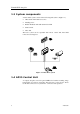
Simrad AP35 Autopilot 1.3 System components A basic AP35 system consists of the following units (refer to Figure 1-1): • AP35 Control Unit with accessories • Heading sensor • Rudder Feedback Unit with transmission link • Junction Unit • Drive unit The basic system can be expanded with remote control unit, hand held remote and steering lever. Figure 1-1 AP35 Basic system 1.4 AP35 Control Unit A compact autopilot control for panel, bulkhead or bracket mounting.
General Information 1.5 Junction units The junction unit is the central in the AP35 autopilot system. It contains the steering computer, interface circuits to all system components and drive circuits for the drive unit motor and clutch. Three models, J300X, J300X-40 and J3000X are available.
Simrad AP35 Autopilot RC25 Rate Compass Fluxgate compass with integrated rate of turn sensor. Provides a dramatic improvement to the dynamic performance of both the autopilot and a stabilized radar display. Same dimensions as RFC35. Magnetic Compass Most liquid filled magnetic compass with external 2 axis gimbals can be interfaced by using CD100A (CD109) Course Detector and CDI35 Course Detector Interface.
General Information FU50 Follow-Up Steering Lever The FU50 Follow-up steering lever features a dial (scale) with 5° rudder angle markings. The rudder will move and stop at the angle selected on the dial. The FU50 has a mid-position indent, buttons for (limited) mode selection, and mode indicators (STBY, FU, AUTO, NAV, WORK, and THRUSTER*). It is designed for indoor and outdoor bulkhead- or panelmounting. Refer to the FU50 manual. * With AP50 Autopilot only.
Simrad AP35 Autopilot This page is intentionally left blank.
Operation 2 OPERATION OF THE AUTOPILOT Caution ! An autopilot is a very useful navigational aid, but DOES NOT under any circumstance replace a human navigator.
Simrad AP35 Autopilot A group of user adjustable settings are provided in the AP35 USER SETUP MENU (page 25). The settings allows adjustment of display visibility, selection of heading sensors, navigation and position sources and the ability to select between automatic or manual adjustable sea state filter. Alarms are presented in plain text to alert you of system and external data failure conditions. Alarms include both audible and visual presentations. The alarm listing is on page 91. 2.
Operation 2.3 Follow-Up steering When both the PORT and STBD push buttons are pressed simultaneously the AP35 is set to Follow-Up steering mode and rudder commands can be set by the course dial. One revolution of the dial equals 45° rudder command. The rudder will move to the commanded angle and stop. PORT STBD Follow-Up mode. Commanded rudder angle: 22° to stbd. Rudder angle:12 FU 22 12 Press both buttons simultaneously to activate Follow-Up Use course knob to command rudder angle.
Simrad AP35 Autopilot 2.7 R3000X Remote Control SIMRAD Push buttons for Port and Stbd NFU commands STBY-AUTO STBY/AUTO mode button. AUTO, WORK or NAV mode is when lamp is lit Note! When in AUTO/WORK mode, pressing the buttons will change the set course 1° per push. If you keep the button pressed, it will automatically change the course in increments of 3°/second.
Operation 2.9 Automatic Steering The AUTO mode is used to make the AP35 steer the boat automatically on a set heading. AUTO is always available from any mode or function within the AP35 by a single push on the AUTO button. When the AUTO mode is selected, the AP35 automatically selects the current boat heading as the set course and the current rudder angle to compensate for wind/current. Note ! If Init Rudder “Midship” is selected (see Dockside settings, page 71 the rudder will move to midship (0°).
Simrad AP35 Autopilot 2.10 Automatic Speed selection The AP35 provides two different sets of steering parameters for controlling the response of the boat at different speeds (HI or LO) while in AUTO and NAV modes. The AP35 always selects the HI speed steering parameters when first switched on. This is a safety feature.
Operation 2.12 Navigating with the AP35 The AP35 has the capability to use steering information from an external navigator (GPS, Chart Plotter) to direct the boat to a specific waypoint location, or through a route of waypoints. In the NAV mode, the AP35 uses the heading sensor as it's source of heading for course keeping. The steering and speed information received from the external navigator alters the set course to direct the AP35 to the destination waypoint.
Simrad AP35 Autopilot When operating the AP35 in NAV mode to automatically steer through a route of waypoints, the AP35 will steer to the first waypoint in the route after you accept the first waypoint as the location to steer to. When you arrive at the waypoint, the AP35 will display an alert screen with the proposed new course information displayed. If the required course change is more than 10° you will need to verify that the upcoming course change is acceptable.
Operation 2.13 WORK-mode The WORK-mode is an automatic steering mode to be used under operational conditions different from those normally found when a vessel is in transit on a preset course. Examples are trawling, towing, trolling on one engine, slow speed etc. First Press Second Press W 313 315 WORK ADJ 02 W315 Rudder angle Set course LO WORK ADJ At such incidents some boats may need a rudder off-set when steered by hand.
Simrad AP35 Autopilot 2.14 TURN-mode The AP35 provides special turn features when in AUTO or WORK modes. U-Turn changes the current set course to be 180 degrees in the opposite direction. The user may decide if the U-Turn should be made to Port or Starboard to bring the boat on the new course. U-Turn is activated by a single push on the TURN button. After the single push, the AP35 will continue on the set course until you press either the PORT or STBD button to select the direction to make the U-Turn.
Operation 2.15 Dodging The AP35 also provides the capability for dodging. Dodging is useful in situations where you need to quickly take control of the helm to steer around an obstruction, and then wish to return on the previous set heading after performing the evasive manoeuvre. A quick double press on the TURN/DODGE button activates dodging. When in DODGE mode the course displayed is the current boat's heading, however, the previous set course is remembered by the AP35.
Simrad AP35 Autopilot 2.17 Lock function The "LOCK" function is a safety feature included in the AP35 system to disable all control units except for a single, user selected control unit location. When the "lock" function is in use, no transfer of command may take place; only the "active" control unit stays in command. To enable the "lock" function, make a quick double press on the STBY button.
Operation 2.18 User Set-up Menu Quick double press Backlight 03 NAV SETUP Displays User Set-up Menu Enter User Setup Menu STBD STBD - SETUP - - SETUP Backlight 03 - SETUP Contrast 05 - SETUP Select Comp.: RFC COMP. - SETUP Seastate Filt.: OFF - SETUP NAV. source: GPS 1 - SETUP POS. Source: GPS 1 BACK FWD PORT Scrolls through menu selections or sets value on menu items Sequences FWD in MENU Sequences BACK in MENU Adjust backlight of display and pushbuttons (10 steps, 10 = brightest).
Simrad AP35 Autopilot This page is intentionally left blank.
Technical Specifications 3 TECHNICAL SPECIFICATIONS 3.1 AP35 Autopilot System Boat size and type: .........................Up to 45 feet, Power Steering system types: ....................Hydraulic, Mechanical, Solenoids Inter-unit connection: .....................ROBNET network or two-wire supply/data System ON/OFF:............................From control units Supply voltage:...............................See junction units Power consumption: .......................
Simrad AP35 Autopilot 3.2 AP35 Control Unit Dimensions:....................................See Figure 3-1 Weight: ...........................................0,9 kg (2.0 lbs) Display: Type:.......................................Backlit LCD matrix display Resolution:..............................80 x 32 pixels Color:..............................................Black Illumination: ...................................Adjustable in 10 steps Environmental Protection:..............IP56 Safe distance to compass:..
Technical Specifications Rudder feedback input: ..................Frequency signal, 3400 Hz., 20 Hz/deg. Rudder feedback units:...................RF300 or RF45X NMEA input/output ports:..............J3000X: 1 (one) J300X, J300X-40: 2 (two) External Alarm: ..............................Open collector Temperature range: Operation: ............................... 0 to +55 °C (+32 to +130 °F) Storage:...................................–30 to +80 °C (–22 to +176 °F) Mounting: ...................................
Simrad AP35 Autopilot 3.4 RFC35 Fluxgate compass Dimensions:....................................See Figure 3-4 Weight: ...........................................0,9 kg (2,0 lbs) Supply and output:..........................Polarity independent 2-wire supply with superimposed pulse width modulation Automatic Performance: Calibration: .............................Automatically activated by control head Gain compensation: ................Automatically adjusted continuously Repeatability:......................
Technical Specifications 3.5 RC25 Rate Compass Dimensions:....................................See Figure 3-4 Weight: ...........................................0,9 kg (2,0 lbs) Power consumption: .......................0,9 watts Supply and interface:......................Robnet Environmental Protection:..............IP56 Material: .........................................White ABS Temperature range: Operation:.............................0 to +55 °C (+32 to + 130 °F) Storage: ..............................
Simrad AP35 Autopilot 3.7 RI35 Mk2 Rudder Angle Indicator Dimensions:...............................See Figure 3-5 Weight: ......................................1.0 kg Supply voltage:..........................12/24V DC –25%/+30%, polarity independent Power consumption: ..................Max 3 W Input signal:...............................Frequency 3400 Hz (midship reference), ±20Hz/degree, polarity independent Current: 0.1 - 1.1mA (midship 0,6mA), polarity independent NMEA 0183 RSA (min. 10 Hz) $--RSA,x.
Technical Specifications 3.8 RF300 Rudder Feedback Unit Dimensions:....................................See Figure 3-6 and Figure 3-7. Weight: ...........................................0,5 kg (1,1 lbs) Rudder angle: .................................± 90 degrees Output signal: .................................Polarity independent frequency signal Frequency resolution: .............Centre: 3400 Hz, 20 Hz/degree of change Linearity: ± 3 degrees up to 45 degrees of rudder Cable supplied: ......................
Simrad AP35 Autopilot 3.9 RF45X Rudder Feedback Unit Dimensions:....................................See Figure 3-8 Protection: ......................................IP56 Ambient temperature:.....................–10 - +55°C Operating voltage: ..........................12V DC (autopilot supplied) Frequency output, Feedback: .........3400Hz (midship reference) Port: +20Hz/degree, stbd: -20Hz/degree Current output, Indicator ................0.1mA - 1.1mA Capacity:.........................................
Technical Specifications 3.10 R3000X Remote STBY AUTO SIMRAD R3000X Dimensions:......................................... See Figure 3-10 Weight: ................................................. 0,4 kg (0,9 lbs) Material: ..........................Epoxy-coated aluminum Protection .............................................................. IP56 Safe distance to compass: ..................... 0.15 m (0.5 ft.) Temperature range: Operating: ..................–25 to +55°C (–13 to +130°F) Storage: ........
Simrad AP35 Autopilot Output (valid when used with AP35) Robnet...................................................................................Heading T & M, speed, NFU Analog sin/cos ......................................................................................................0-5V DC Step 6 step/°, max rate 20°/sec: ................................................................. 24V DC, 20mA Simrad (Anritsu)/Furuno clk/data for 2 radars .....................................
Technical Specifications Robnet network interface: ................................................................ 2 network connectors Cable inlets: ........................................................Rubber glands for cable diam 10-14 mm Mounting: ................................................................................................. Bulkhead mount Material:......................................................................................
Simrad AP35 Autopilot 3.14 FU50 Steering Lever Dimensions:.......................See Figure 3-13. Handle can be mounted pointing upwards or downwards. Weight: ..............................1.2 kg (2.6 lbs.) including cable Material: ............................Polyacetal (POM) Environmental protection: .IP56 Power consumption: .........3W Safe distance to compass:..0.15 m (0.5ft.) Temperature: Operating:................–10 to +55°C (+14 to +130°F) Storage: ...................
Technical Specifications 3.15 IP protection Each part of a Simrad autopilot system has got a two digits IP protection code. The IP rating is a method to classify the degree of protection against solid objects, water ingress and impact afforded by electrical equipment and enclosures. The system is recognised in most European countries and is set out in a number of British and European standards.
Wind_Data Apparent wind angle Apparent wind speed Depth_Data Depth ref transducer Transducer-Keel Offset Depth range Speed_Temp_Data Gps_Data Nav_Data 1 IS11 illumination IS15 RX: IS15 TX: Transmission interval in sec.-> If Instr.
Installation 4 INSTALLATION 4.
Simrad AP35 Autopilot c) Compass Offset adjustment d) Automatic tuning (Optional: does not need to be done) e) Viewing parameters 10. Testing Autopilot Operation at Sea (refer to Sea Trial instructions, page 86) 11. Provide the user with training (Page 87) 4.3 Unpacking and handling Care should be taken when unpacking and handling the equipment.
Installation 4.5 AP35 System Layout Figure 4-1 AP35 System layout with options 4.6 RF300 Rudder feedback The RF300 Rudder feedback unit mounts close to the rudders, and is mechanically linked to the rudder tiller arm or rudder quadrant. Refer to Figure 4-2 for the recommended mounting arrangement. Note that the RF300 transmitter arm has two slots for the transmission link. The slots enable maximum flexibility to provide the 1:1 mechanical linkage relationship.
Simrad AP35 Autopilot Note ! Carefully observe the alignment marks. A rudder feedback alarm may be the result if the alignment instructions as per Figure 4-2 are neglected. Attach the transmitter rod to the RF300. Set the RF300 mounting location to be in accordance with Figure 4-2. The centre of the RF300 should be in line with the centre of the rudder post. Mount the RF300 to a suitable platform using the screws provided.
Installation 4.7 RF45X Rudder Feedback Unit The RF45X is normally installed with the shaft pointing upwards. It can, however, be mounted with the shaft pointing downwards if this is more convenient. The deflection can then be inverted as illustrated in Figure 4-5. An “upside-down” installation will make access to within the unit more convenient as the unit can be opened without moving it from the mounting base. To open the unit, unscrew the two screws at the bottom and remove the cover.
Simrad AP35 Autopilot Electrical connection Use a twisted pair cable AWG20 (0.5 mm2) between the breakout box and the J3xx junction unit. The cable length is not critical but should be kept at a minimum. The cable should be connected to the junction unit according to Figure 4-5. When splicing the cables in the breakout box, crimp the enclosed pins on each wire of the extension cable. Otherwise the wires may be cut off at the terminal point when the screws are tightened.
Installation 4.8 Junction unit The junction unit is designed to operate in a location that provides ambient temperatures below +55°C (+130°F). Note ! The junction units (J3000X, J300X and J300X-40) are not water proof and should be mounted vertically as shown in a dry place between the control unit and the drive unit. Figure 4-6 J3XX mounting Cable connections Use only shielded cables. This includes Mains input, drive units and if necessary for the extension of the RF300 Rudder Feedback cable.
Simrad AP35 Autopilot Grounding and RFI The AP35 system has very good RFI protection and all units are using the Junction Unit as common ground/shield connection. The Junction Unit should therefore have a proper ground connection to the hull. ROBNET cables and other signal cables (compass, feedback, NMEA) should not be run in parallel with other cables carrying RF or high current, such as VHF and SSB transmitters, battery chargers/generators and winches.
Installation Main Board terminals 4.9 Drive unit The relation between drive units, drive unit voltage, input voltage, drive output and interfacing to steering gear are shown in the table below. The AP35 system detects whether a reversible motor or a solenoid is connected and outputs the correct drive signal automatically. Refer to the connecting diagram for the different drive units on page 51 onwards. Installation instructions for the drive units are found in the manual for the individual units.
Simrad AP35 Autopilot LINEAR DRIVE UNITS MODEL MOTOR JUNCTION MAX PEAK MAX HARDPWR. TILLER VOLTS UNIT STROKE THRUST RUDDER OVER CONARM mm (in.) kg (lb.) TORQUE TIME SUMP. mm Nm sec. (in.) (lb.in.
Installation Note ! When selecting DRIVE UNIT voltage in the Installation setup, the clutch/bypass voltage is always set equal to the motor voltage. If a retrofit installation where e.g. a HLD2000 has a 12V motor and a 24V bypass valve, the bypass valve solenoid has to be changed back to standard 12V version. Connecting a reversible pump JUNCTION UNIT POWER PCB TB1 TB2 TB3 TB4 TB5 TB6 Sol. -Motor Sol.
Simrad AP35 Autopilot Connecting a solenoid valve JUNCTION UNIT SOLENOID VALVE POWER PCB TB1 TB2 TB3 TB4 TB5 TB6 Sol. gnd Sol. gnd Sol. -Motor Sol. -Motor Sol. TB7 Sol. Figure 4-10 Connecting a solenoid valve 4.10 Control unit Avoid mounting the control unit(s) where it is easily exposed to sunlight, as this will shorten the lifetime of the display. Panel mounting • Make a panel cut-out of 210x102 mm. • Use the supplied fastening device to fasten the control unit to the panel.
Installation • Remove the Control unit, drill the 4 mounting holes in the mounting surface. • Unbolt the temporarily fitted bracket halves and screw them to the mounting surface. • Assemble the complete bracket again and adjust the control head to best viewing angle and tighten up the mounting bracket bolts. • Connect the Robnet cables to the control unit connectors (See note on next page).
Simrad AP35 Autopilot CONTROL UNIT CONTROL UNIT JUNCTION UNIT CONTROL UNIT CONTROL UNIT JUNCTION UNIT NI300X NI300X All connectors are crimp type, which can be easily dismantled if required in an installation where you can not drill holes as big as the connector is. See table for pin configuration and color code of the network cable.
Installation HOW TO REMOVE PINS: Extraction tool Pull the wire Insert tool in slot Note ! For installations that require special cable length, contact your Simrad distributor for information. 4.11 RFC35 Fluxgate Compass Figure 4-14 RFC35 mounting The heading sensor is the most important part of the AP35 system and great care should be taken when deciding the mounting location.
Simrad AP35 Autopilot If the RFC35 is deck mounted or bulkhead mounted athwart ship with the cable gland pointing aft, little if any offset correction is required. With the cable gland pointing forward a 180° correction is required. When mounting RFC35 on a bulkhead along ship, a +90° or -90° correction is needed dependent on whether it is a port or starboard bulkhead.
Installation • Connect the Robnet connector to the AP35 Control Unit (or GI51 or NI300X if installed), see Figure 4-16. • Alternatively, if there is no free receptacle, cut the connector from cable and connect the wires in parallel with the wires going from junction unit to the control unit (see Figure 4-13). Do not connect yellow and the green wires and ensure that they do not connect with terminal or chassis. the the the the • Select RFC = ROBNET in the Installation : Interface Setup.
Simrad AP35 Autopilot 4.15 S35 NFU Steering Lever The unit is mounted to bulkhead or panel by two screws from the front. The cable is connected to the junction unit according to Figure 4-18. Interchange the port and stbd wires to the screw terminals in the junction unit if necessary to make the direction of the lever movement coincide with the direction of the rudder movement.
Installation 4.17 RI35 Mk2 Rudder Angle Indicator The RI35 Mk2 is designed for flush, bulkhead or bracket mounting, and should be positioned in a location in clear view of the helmsman. Mounting of RI35 Mk2 is identical to the mounting of AP35 Control Unit; refer to page 52. When the location is determined, the cables should be connected to RI35 Mk2 before the unit is mounted. The interconnection cables are screened, and the screen should be grounded in the autopilot junction unit.
Simrad AP35 Autopilot Reversed deflection On installations where the rudder feedback unit is mounted upside down, the deflection of the pointer will be reversed. To make it correct, move the rudder to approximately 10° either way then press and hold the illumination key for 10 (ten) seconds. The pointer will then first travel to zero then continues to the opposite side of the scale confirmed by a 2-second beep.
Installation 4.20 Double NMEA input/output JUNCTION UNIT GPS/PLOTTER MAIN PCB POWER PCB TB8 GPS/PLOTTER TB9 TB13 TB10 NMEA COMPASS NMEA Input2 TB14 NMEA Output1 NMEA Output2 NMEA Input 1 Gnd RX1 Sys. Sel. RX1+ Vbat+ TX1+ TX1 TX2 RX2 TX2+ RX2+ Figure 4-22 Double NMEA connection 4.21 Additional NMEA output on Port 2 Output signal Output terminal Continuous output of compass heading on 10 Hz (10x/sec.
Simrad AP35 Autopilot 4.23 Radar Clock/Data ANRITSU OR FURUNO RADAR J300X JUNCTION UNIT POWER PCB TB8 TB9 TB10 Clk_c Clk_h Data_h Data_c R ad ar Figure 4-24 Radar Clock/Data connection 4.24 IS15 Instrument For installation and operation of the IS15 instruments refer to separate manuals. NMEA In This connection will provide speed and depth input to the autopilot. If an IS15 Wind Transducer is connected to the system, wind information will also be transferred to the autopilot.
Installation Figure 4-25 IS15 Instruments / J3XX Connection Figure 4-26 IS15 Expander / J3XX Connection 4.
Simrad AP35 Autopilot 4.26 Digital Repeater Figure 4-28 DR75 Digital Repeater connection 4.27 External Alarm The external alarm circuit has an open collector output for an external alarm relay or buzzer. The alarm voltage is the same as the main supply voltage. Max. load on external alarm output is 0.9 Amp. J300X/J300X-40 JUNCTION UNIT POWER PCB TB6 TB8 TB7 TB9 Ext.
Installation 4.28 NI300X NMEA Interface Unit The NI300X is normally installed inside a console or locker close to Nav receivers, radar and instruments to keep cables short. The unit does not have controls that need to be operated during installation or use, but you should be able to take the lid off for inspections, to view LED indication of received signals. It should be installed with the cable inlet and the Robnet connectors facing down.
Simrad AP35 Autopilot Alarm TB6 ALARM OUTPUT (Normally open) TB5 Furuno Clk C Clk H SIMRAD FURUNO RADAR DISPLAY N.C. DataC DataH TB4 TB11 NMEA4 TX- IS15 INSTRUMENTS SIMRAD TB11 TX+ RX- TB7-B RX+ TB7-A SIMRAD +12V EXTERNAL TB3 TX- NMEA3 SIMRAD IS15 EXPANDER OUTPUT FOR RADAR, INSTRUMENTS ETC.
Installation Note ! Gyros with stepper or geared synchro output can not be used when GI51 is connected to AP35 via Robnet. Then GI51 must be installed as a stand alone unit, using NMEA heading output to J3XX port #2. Figure 4-31A GI51 Alternative connection Note ! For heading offset and alignment, see GI51 Manual. 4.31 CD100A Course Detector On some installations the owner may prefer to use the boats own compass. The compass must be fully gimballed and have a flat surface underneath to fit the CD100A.
Simrad AP35 Autopilot 4.32 CDI35 Interface Locate the CDI35 as close to the compass as possible so that there will be no problem finding it in the event of a service. Put the two fixing screws in the slots and secure the unit to the bulkhead. Open the unit to access the screw terminals. Connect the cables as shown on the diagram below. Figure 4-33 CDI35 connection Note ! CD100 has a connector that has to be cut off the cable. 4.
Installation • Seatrial Settings: Determines automatic calibrations and steering parameters • View Parameters Permits viewing, setting, or changing steering parameters Each group is designed to focus on specific functions related to an installation activity, and enable quick access when changes need to be made.
Simrad AP35 Autopilot On new installations, and whenever a control unit, junction unit, or software is replaced in an AP35 system, it is recommended that a MASTER RESET be performed as described in the ISM prior to proceeding with the setup procedure. When using the ISM refer to diagram "Installation settings Menu Flow Chart" on next page.
Installation Language selection The AP35 can present the display in eight different languages: • English, Norsk, Francais, Espanol, Italiano, Nederlands, Svenska and Deutsch. To access the language selection in the ISM: 1. Turn on the equipment and wait approx. 5 seconds. 2. Press the NAV/setup button for about 5 seconds until the display is changed to: INSTALLATION Language English 3. Turn the course dial until the language you wish to use is displayed. 4.
Simrad AP35 Autopilot Type of boat will affect the steering parameters, and the functions available in the autopilot system. Select appropriate boat type and press STBD [>] button. Drive unit voltage selection This menu option requires the installer to set the drive unit voltage to the correct level. The selections are 12V, 24V or 32V and should be set to the voltage specified for your drive unit.
Installation 4. Press the STBY button again if necessary to read the rudder angle display (You may also access the User menu and the SYSTEM DATA menu item to read the rudder angle). 5. Use a flat screwdriver in the slot and adjust the rudder angle to zero degrees on the display. 6. Secure the transmission lever to the shaft and proceed with the ‘Rudder Feedback Calibration’. Note ! If the autopilot presents you with a Rudder Feedback Alarm after turn on, proceed as follows: • Turn the autopilot off.
Simrad AP35 Autopilot Manually turn the helm wheel to port until the rudder stops at maximum port rudder. INSTALLATION Turn rudder max. PORT 039 Adjust? Adjust the displayed angle the same way as for starboard adjustment. (This time you need not correct for wrong side if the Rudder Feedback is upside down). Note ! Rudder zero may still be wrong but will be adjusted later during Sea Trial. Proceed to next menu item by pressing STBD [>] button.
Installation Transition Speed INSTALLATION Transition speed: 00 kn The transition speed is the speed where the AP35 will automatically change the steering parameter set from the HI speed to LO speed parameters, or vice versa. The default setting of transition speed is zero, which requires that steering parameter selection be done manually.
Simrad AP35 Autopilot Initial Rudder When Actual is selected, the autopilot will use the current rudder position as midship reference (bumpless transfer) when switching from Stby to Auto or Nav. (or Dodge). When Midship is selected the autopilot will use zero degrees as midship reference. Hence, the rudder will always move to midship when switching from Stby (or Dodge) to Auto or Nav mode.
Installation Abbreviated name Equipment / Usage NOTES GPS1 Primary GPS GPS2 Backup GPS LC 1 Primary Loran Can be used as either NAV source or POS source. Also for VTG data for automatic AUTO HI/LO speed selection LC 2 Backup Loran NAV1 Chart plotter NAV2 Other Nav source INSTR Source of data for automatic HI/LO Uses log input (VHW) for speed parameter selection data RFC For use when selecting between Simrad fluxgate compasses RFC35 fluxgate compass is connected to J3xx junction unit.
Simrad AP35 Autopilot The following display will be presented: INSTALLATION Interface Setup? To access the Interface Setup items, turn the course selector clockwise. The display will show: INSTALLATION Input: GPS1: The display is now showing the first name on the list. Assign a hardware port to the name by turning the course selector until the hardware port is displayed. Proceed to the names on the list that shall be assigned by pressing STBD [>] button.
Installation Interface setup - input signal Setup item (abbrev.
Simrad AP35 Autopilot Setup item (abbrev.
Installation 4.34 Sea Trial The Sea-trial menu can only be accessed if the Dockside Settings are done and confirmed. It is also recommended that the Interface Setup be performed prior to Seatrial settings.
Simrad AP35 Autopilot Compass calibration This function will activate the automatic compass calibration procedure. Note ! The GI51 Gyro Interface is pre-calibrated for Simrad RGC gyro compasses. When other gyro compasses with synchro 1:1 is connected to GI51, it is recommended to perform the automatic compass calibration in order to calibrate the GI51 Interface/input signal.
Installation The following display is presented when accessing the COMPASS OFFSET entry screen: INSTALLATION Offset ?: 000° Heading : 194° Dial in the correction by turning the course dial to offset the RFC35 heading to agree with the known, accurate heading. The offset value can be either positive or negative.
Simrad AP35 Autopilot INSTALLATION INSTALLATION INSTALLATION Automatic tuning? Automatic tuning Autotuning confirmed Activate the AUTOTUNE, by rotating the course selector clockwise. After the Autotune has been completed the rudder must be controlled manually, as the mode is returned to STBY. When the Autotune has been completed, there should normally be no need for further adjustments.
Installation Manual parameter adjust Displayed parameter BOAT TYPE: Displacement Use course dial to adjust parameters PORT STBD Planing Own boat Autotune Manual LOw speed Rudder LO 0.5 0.3 Cont Rudd LO 1.4 1.4 Autotrim LO 40 40 Rudder lim LO 20 20 Rudder HI 0.35 0.2 Cont Rudd HI 1 1 40 40 20 20 0.5 0.
Simrad AP35 Autopilot Counter Rudder is the parameter that counteracts the effect of the boats turn rate and inertia. For a short time period it is superimposed on the normal rudder response as provided by the Rudder parameter. It may sometimes appear as if it tends to make the rudder move to the wrong side (counter rudder). The best way of checking the value of the Counter Rudder setting is when making turns. The s illustrates the effects off various Counter Rudder settings.
Installation • Try the Dodge function, the U-turn and the C-turn. • If a Non-Follow Up lever (or handheld remote) is connected, test the mode switching and verify Port and Stbd steering commands of the lever. • Set waypoints into each navigator connected to the system, and verify that the AP35 steers in NAV mode for each NAV source. • Provide the owner with user training. 4.
Simrad AP35 Autopilot 5 MAINTENANCE 5.1 Control unit The AP35 Control Unit will under normal use require little maintenance as the cases are made from seawater resistant aluminium and has a polyester coating to withstand the rigours of an exposed cockpit. If the unit requires any form of cleaning, use fresh water and a mild soap solution (not a detergent). It is important to avoid using chemical cleaners and hydrocarbons such as diesel, petrol etc.
Maintenance 5.6 Exchange of software programme Junction Unit EPROM Figure 5-1 J3000X/J300X/J300X-40 Main PC-Board AP35 Control Unit EPROM Figure 5-2 AP35 PCB, component layout • Remove the EPROM from the socket by means of the special extraction tool (p/n 44139806) • Insert the tool by pressing the two grip pins down into the two slots in the corners of the socket. • Squeeze the tool and pull out the EPROM. • When inserting new EPROMS, make sure the cut-off corner matches with the one in the socket.
Simrad AP35 Autopilot • The identification tag indicates: - Name of unit - Simrad Egersund part number - Software version Caution ! Cut-off corner Identification tag Make sure that the right EPROM is mounted in the actual unit. EPROM for AP35 Control Unit: P/N 22082978 EPROM for J300X, J300X-40 and J3000X Junction units: P/N 22081640 Slots • After change of EPROM, perform a master reset as described on page 76. Modification on AP35 PCB Refer to our Technical bulletin no. 10/97.
Trouble Shooting 6 TROUBLE SHOOTING An autopilot is a complex system and the performance is dependent of a proper installation and a successful sea trial. In the event of a failure, you will be helped by the AP35 software which contains several test features that will assist you in isolating a probable fault. Audible and visual alarms are given in the event a fault is detected. The audible alarm is reset by pressing any button (e.g. by changing mode from AUTO to STBY).
Simrad AP35 Autopilot Display readout Rudder test failed (cont’d) Compass data missing Probable fault Rudder test not completed within 2 min. a) Poor connections to drive unit b) Faulty Main PCB in junction unit c) Faulty Power PCB in junction unit Rudder moves at full speed to one side. a) Faulty Power PCB in junction unit No data from selected compass. Comm. failure active Control Active control unit (including FU35) goes silent.
Trouble Shooting Display readout Probable fault Recommended action Bypass/clutch overload Clutch/bypass current exceeds 2,5 Amps (overload or short circuit). 1. Check actual current 2. Check voltage marking on coil 3. Check coil resistance (through connecting wires) Bypass/clutch disengaged Poor connection or open circuit in bypass/clutch coil 1. Check connections 2. Replace bypass/clutch if open. 3. Perform new "Rudder test". J3XX high temp.
Simrad AP35 Autopilot 6.2 NMEA Test The NMEA test menu is accessed from the User Set Up Menu (page 25). It provides you with status information of the different NMEA messages used in the system. Decoding - SETUP - The incoming signals are decoded according to a built in priority table. NMEA TEST? Cross Track and bearing information is taken from the NMEA messages with highest priority.
Trouble Shooting 6.3 System Data Menu The menu is accessed from the User Set up Menu (page 25). It provides you with additional system data that can be useful when testing or trouble shooting the system. NMEA hardware test On the Main PCB in the junction unit disconnect the cables and connect TX1+ to RX1+ and TX1- to RX1-. Similar on the Power PCB connect the NMEA ports the same way; TX2+ to RX2+ and TX2– to RX2– (not available on J3000X).
Simrad AP35 Autopilot 7 SPARE PARTS LIST 22085104 22082945 22082853 22082895 22082804 22082978 AP35 Control Unit AP35 Front Housing Ass’y Back cover AP35 Front Panel Keypad AP35 Board Ass'y PROM (programmed) V..R..
Spare Parts List 22011183 22011431 22504039 44156925 RF45 Transmission Link Ass’y RF45 Ball Joint Ass’y Transmission Lever Junction Box (Hensel D1202) NI300X NMEA Interface 22089536 22081913 22081921 NI300X NMEA Interface NI300X PCB Ass'y NI300X PROM V..R..
Simrad AP35 Autopilot 44139707 44139806 44161792 22088595 98 Tools Key for Lock ring on Robnet receptacles Extraction tool for PROM Robnet pin extraction tool (for crimp type connectors) Programming kit RS232 22083083K