
Instruction manual


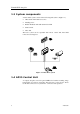
Table Of Contents
- SIMRAD AP35 AUTOPILOT
- DOCUMENT HISTORY
- 1 GENERAL INFORMATION
- 2 OPERATION OF THE AUTOPILOT
- 2.1 Overview
- 2.2 ON/OFF - Standby mode
- Follow-Up steering
- 2.4 Non-Follow-Up steering
- 2.5 NFU Steering lever
- 2.6 NFU Push button remote control
- 2.7 R3000X Remote Control
- 2.8 S35 NFU Steering Lever
- 2.9 Automatic Steering
- 2.10 Automatic Speed selection
- 2.11 Manual speed selection
- 2.12 Navigating with the AP35
- 2.13 WORK-mode
- 2.14 TURN-mode
- 2.15 Dodging
- 2.16 Multiple station system
- 2.17 Lock function
- 2.18 User Set-up Menu
- 3 TECHNICAL SPECIFICATIONS
- 3.1 AP35 Autopilot System
- 3.2 AP35 Control Unit
- 3.3 Junction units
- 3.4 RFC35 Fluxgate compass
- 3.5 RC25 Rate Compass
- 3.6 CDI35 Course Detector Interface
- 3.7 RI35 Mk2 Rudder Angle Indicator
- 3.8 RF300 Rudder Feedback Unit
- 3.9 RF45X Rudder Feedback Unit
- 3.10 R3000X Remote
- 3.11 GI51 Gyro Interface
- 3.12 NI300X NMEA Interface
- 3.13 S35 NFU Steering Lever
- 3.14 FU50 Steering Lever
- 3.15 IP protection
- 4 INSTALLATION
- 4.1 General
- 4.2 Installation checklist
- 4.3 Unpacking and handling
- 4.4 Determine system configuration
- 4.5 AP35 System Layout
- 4.6 RF300 Rudder feedback
- 4.7 RF45X Rudder Feedback Unit
- 4.8 Junction unit
- 4.9 Drive unit
- 4.10 Control unit
- 4.11 RFC35 Fluxgate Compass
- 4.12 RC25 Rate Compass
- 4.13 R3000X Remote Control
- 4.14 FU50 Steering Lever
- 4.15 S35 NFU Steering Lever
- 4.16 F1/2 Remote Control
- 4.17 RI35 Mk2 Rudder Angle Indicator
- 4.18 Interfacing
- 4.19 Single NMEA input/output
- 4.20 Double NMEA input/output
- 4.21 Additional NMEA output on Port 2
- 4.22 Input from “NMEA Compass”
- 4.23 Radar Clock/Data
- 4.24 IS15 Instrument
- 4.25 Analog Repeater
- 4.26 Digital Repeater
- 4.27 External Alarm
- 4.28 NI300X NMEA Interface Unit
- 4.29 CI300X Compass Interface
- 4.30 GI51 Gyro Interface
- 4.31 CD100A Course Detector
- 4.32 CDI35 Interface
- 4.33 Software Setup Procedure
- 4.34 Sea Trial
- 4.35 Final sea trial
- 4.36 Providing user training
- 5 MAINTENANCE
- 6 TROUBLE SHOOTING
- 7 SPARE PARTS LIST

Simrad AP35 Autopilot
4 22083083K
3.4
RFC35 Fluxgate compass....................................................................................... 30
3.5 RC25 Rate Compass............................................................................................... 31
3.6 CDI35 Course Detector Interface ........................................................................... 31
3.7 RI35 Mk2 Rudder Angle Indicator......................................................................... 32
3.8 RF300 Rudder Feedback Unit ................................................................................ 33
3.9 RF45X Rudder Feedback Unit ............................................................................... 34
3.10 R3000X Remote ..................................................................................................... 35
3.11 GI51 Gyro Interface................................................................................................ 35
Input (valid when used with AP35)........................................................................ 35
Output (valid when used with AP35) ..................................................................... 36
3.12 NI300X NMEA Interface ....................................................................................... 36
3.13 S35 NFU Steering Lever ........................................................................................ 37
3.14 FU50 Steering Lever............................................................................................... 38
3.15 IP protection ........................................................................................................... 39
4 INSTALLATION................................................................................................................. 41
4.1 General.................................................................................................................... 41
4.2 Installation checklist............................................................................................... 41
4.3 Unpacking and handling......................................................................................... 42
4.4 Determine system configuration............................................................................. 42
4.5 AP35 System Layout.............................................................................................. 43
4.6 RF300 Rudder feedback ......................................................................................... 43
4.7 RF45X Rudder Feedback Unit ............................................................................... 45
Electrical connection .............................................................................................. 46
4.8 Junction unit ........................................................................................................... 47
Cable connections................................................................................................... 47
Grounding and RFI................................................................................................. 48
Junction unit terminals............................................................................................ 48
4.9 Drive unit................................................................................................................ 49
Connecting a reversible pump ................................................................................ 51
Connecting a hydraulic linear drive........................................................................ 51
Connecting a solenoid valve................................................................................... 52
4.10 Control unit............................................................................................................. 52
Panel mounting....................................................................................................... 52
Bracket mounting ................................................................................................... 52
ROBNET network cables ....................................................................................... 53
4.11 RFC35 Fluxgate Compass...................................................................................... 55
4.12 RC25 Rate Compass............................................................................................... 56
4.13 R3000X Remote Control........................................................................................ 57
4.14 FU50 Steering Lever............................................................................................... 57
4.15 S35 NFU Steering Lever ........................................................................................ 58
4.16 F1/2 Remote Control .............................................................................................. 58
4.17 RI35 Mk2 Rudder Angle Indicator......................................................................... 59
RI35 Mk2 illumination ........................................................................................... 59
Zero adjust .............................................................................................................. 59
Reversed deflection ................................................................................................ 60
4.18 Interfacing............................................................................................................... 60
4.19 Single NMEA input/output..................................................................................... 60
4.20 Double NMEA input/output ................................................................................... 61