
Instruction manual


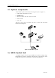
Table Of Contents
- SIMRAD AP35 AUTOPILOT
- DOCUMENT HISTORY
- 1 GENERAL INFORMATION
- 2 OPERATION OF THE AUTOPILOT
- 2.1 Overview
- 2.2 ON/OFF - Standby mode
- Follow-Up steering
- 2.4 Non-Follow-Up steering
- 2.5 NFU Steering lever
- 2.6 NFU Push button remote control
- 2.7 R3000X Remote Control
- 2.8 S35 NFU Steering Lever
- 2.9 Automatic Steering
- 2.10 Automatic Speed selection
- 2.11 Manual speed selection
- 2.12 Navigating with the AP35
- 2.13 WORK-mode
- 2.14 TURN-mode
- 2.15 Dodging
- 2.16 Multiple station system
- 2.17 Lock function
- 2.18 User Set-up Menu
- 3 TECHNICAL SPECIFICATIONS
- 3.1 AP35 Autopilot System
- 3.2 AP35 Control Unit
- 3.3 Junction units
- 3.4 RFC35 Fluxgate compass
- 3.5 RC25 Rate Compass
- 3.6 CDI35 Course Detector Interface
- 3.7 RI35 Mk2 Rudder Angle Indicator
- 3.8 RF300 Rudder Feedback Unit
- 3.9 RF45X Rudder Feedback Unit
- 3.10 R3000X Remote
- 3.11 GI51 Gyro Interface
- 3.12 NI300X NMEA Interface
- 3.13 S35 NFU Steering Lever
- 3.14 FU50 Steering Lever
- 3.15 IP protection
- 4 INSTALLATION
- 4.1 General
- 4.2 Installation checklist
- 4.3 Unpacking and handling
- 4.4 Determine system configuration
- 4.5 AP35 System Layout
- 4.6 RF300 Rudder feedback
- 4.7 RF45X Rudder Feedback Unit
- 4.8 Junction unit
- 4.9 Drive unit
- 4.10 Control unit
- 4.11 RFC35 Fluxgate Compass
- 4.12 RC25 Rate Compass
- 4.13 R3000X Remote Control
- 4.14 FU50 Steering Lever
- 4.15 S35 NFU Steering Lever
- 4.16 F1/2 Remote Control
- 4.17 RI35 Mk2 Rudder Angle Indicator
- 4.18 Interfacing
- 4.19 Single NMEA input/output
- 4.20 Double NMEA input/output
- 4.21 Additional NMEA output on Port 2
- 4.22 Input from “NMEA Compass”
- 4.23 Radar Clock/Data
- 4.24 IS15 Instrument
- 4.25 Analog Repeater
- 4.26 Digital Repeater
- 4.27 External Alarm
- 4.28 NI300X NMEA Interface Unit
- 4.29 CI300X Compass Interface
- 4.30 GI51 Gyro Interface
- 4.31 CD100A Course Detector
- 4.32 CDI35 Interface
- 4.33 Software Setup Procedure
- 4.34 Sea Trial
- 4.35 Final sea trial
- 4.36 Providing user training
- 5 MAINTENANCE
- 6 TROUBLE SHOOTING
- 7 SPARE PARTS LIST

General Information
22083083K 7
1 GENERAL INFORMATION
1.1 Introduction
Congratulations on the purchase of your new Simrad AP35 autopilot system
and thank you for selecting what we feel is the most advanced autopilot
system available on the market today.
Today Simrad manufacture a complete range of autopilots for all types of
vessels, from leisure boats up to advanced steering systems for merchant
marine vessels. Our factory for these products is located in Egersund on the
south/west coast of Norway. The company's involvement in autopilots began
in 1953 with equipment for the North Sea fishing fleet under the brand name
Robertson. Professional mariners around the world acknowledge that the
Robertson and Simrad brand names are synonymous with the absolute best
in autopilot technology.
The AP35 autopilot from Simrad represents yet another step forward in
autopilot technology with the intent to provide small fishing boats and work
boats up to 45 feet with a host of new features. The system can be expanded
and enhanced with a selection of options and accessories.
The brain in the AP35 autopilot system is the single "intelligent" junction
unit that communicates with all other system modules on the ROBNET
network. The ROBNET has been developed to establish a reliable digital
communication and power distribution network between the units in the
system. The ROBNET simplifies installation and enables the AP35 system
to be easily expanded at any time. Any unit that is connected to the autopilot
system via Robnet is called a Robnet Unit (See table on page
9).
1.2 How to use this manual
This manual is intended as a reference guide for operating, installing and
maintaining the Simrad AP35 autopilot. Great care has been paid to simplify
operation and set-up of the AP35, however, an autopilot is a complex
electronic system. It is affected by sea conditions, speed of the vessel, hull
shape and size.
Please take time to read this manual to get a thorough understanding of the
operation and system components and their relationship to a complete AP35
autopilot system.
Other documentation materials that are provided with your system include a
warranty card. This must be filled out by the authorized dealer that
performed the installation and mailed in to activate the warranty.