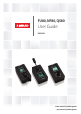
FU80, NF80, QS80 User Guide ENGLISH www.simrad-yachting.com pro.simrad-yachting.
Preface As Navico is continuously improving this product, we retain the right to make changes to the product at any time which may not be reflected in this version of the manual. Please contact your nearest distributor if you require any further assistance. It is the owner’s sole responsibility to install and use the equipment in a manner that will not cause accidents, personal injury or property damage. The user of this product is solely responsible for observing safe boating practices.
Contents 2 Introduction 2 2 3 About this manual Wheelmark approval Parts included 4 Installation 4 6 Mounting Wiring 7 Operation 7 10 12 14 16 16 17 17 Basic operation - all remotes Using the NF80 Using the FU80 Using the QS80 Changing commanded rudder direction Alarms Restoring factory settings Maintenance 18 Changing default settings 18 The main menu 19 Specifications 19 20 Technical specifications Drawings Contents | FU80, NF80, QS80 User Guide |1
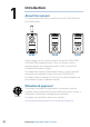
1 Introduction About this manual This manual describes how to install and use the FU80, NF80 and the QS80 remotes. NF80 FU80 QS80 These remotes can be used to remotely control the AP70, AP80, AP24 and AP28 autopilot systems. They can also be used to remotely operate the autopilot function in NSE, NSS and NSO (Simrad Multifunction Displays). For detailed description of operational modes, see the Operator manual for you autopilot system or for your NSE/NSO/NSS.
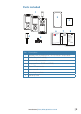
Parts included 1 2 3 6 8 Mounting template User Guide ENGLISH 988-10108-001 www.simrad-yachting.com LIMITED WARRANTY IMPORTANT. Do not use this template if it has been rescaled by copying or printing. If this is not the original, or is a print from a file, please check the dimension lines below are to scale before use. 5 IMPORTANT. Ne pas utiliser ce gabarit s’il a été photocopié ou imprimé en format réduit ou agrandi.
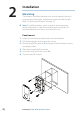
2 Installation Mounting The remotes should be mounted with special regard to the units’ environmental protection, temperature range and cable length. Refer “Technical specifications” on page 19. ¼¼ Note: If installed outdoors, select a position and a mounting option that prevents water from remaining on the display. It is recommended to cover the units when not in use. Panel mount 1. Attach the mounting template to the selected position 2. Drill fastening holes and remove the cut-out 3.
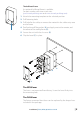
The bulkhead frame 1. 2. 3. 4. 5. 6. An optional bulkhead frame is available. For part number, refer to our web sites (pro.simrad-yachting.com and www.simrad-yachting.
The lever can be mounted in a 180° opposite direction as follows: 1. Remove the knob’s cap (A) 2. Remove the screw (B), and carefully remove the knob (C) 3. Rotate the knob 180°, install the selected lever, re-install the knob and the cap A B C Wiring ¼¼ Note: Don’t make sharp bends in the cables, and avoid running cables in a way that allows water to flow down into the connectors. If required, make drip and service loops. The remotes connect to the CAN bus backbone or SimNet backbone as shown below.
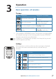
3 Operation Basic operation - all remotes The keys Key CMD STBY Activates/de-activates thrusters * CMD MODE MODE Turn STBY * Take/request command Adjust illumination CMD STBY Long press (3 seconds) MODE CMD STBY Short press the autopilot system to Standby mode Toggle between available modes MODE Toggles day and night display illumination Displays the Main menu (Standby mode only) Only available in AP70/AP80 systems.
The screen The upper part of the screen shows information relevant for the autopilot mode as shown below.
Switching from automatic to manual steering Press the STBY key on active remote to switch the system from automatic mode to Standby mode. If a menu or dialog is open, you must press and hold the STBY key to switch to Standby mode. Turning the unit on/off The remote units have no power key, and will be on as long as connected to a powered CAN-bus/SimNet backbone. If the autopilot system is turned off from an autopilot control unit, the remotes will go to sleep mode.
Taking command Take command by pressing the CMD key. When command is transferred, the autopilot system will remain in current mode. For more information about multi stations, see the Operator Manual for your autopilot system. In an open system (no command transfer restrictions), you will get immediate control on the remote unit requesting command. In a multi-station system with active lock function, the command request must be confirmed on the active control unit before you can use the remote.
Mode selection You toggle between available modes by repeated pressing the MODE key. The selection times out and triggers the mode shift. When in any other mode than NFU, the first press on the MODE key will turn the system to NFU mode. You switch to Standby from any mode by pressing the STBY key. Non-follow up steering In this mode you use the lever to move the rudder. The rudder will move in the same direction as the lever, and will move as long as the lever is moved from mid-position.
Using the FU80 The FU lever can be rotated 70° to port and starboard from midposition. The lever will remain in set position, and the commanded rudder angle/heading change maintained until the lever is returned to mid-position. You can use the FU80 in FU, AUTO and NoDrift mode. You can also get command if the system is in NFU, NAV or Wind mode, but you cannot operate these modes from the FU80.
Follow-up steering In FU mode you use the lever to set the commanded rudder angle. Warning: To avoid unintended rudder movement you should observe the lever position (commanded rudder angle) before activating the FU mode! To increase resolution on small rudder angle commands, the relation between the lever rotation and the commanded rudder angle is non-linear. When the lever is rotated 20° from mid-position the rudder will be commanded 5° to port or starboard. A 65° lever angle will move the rudder to 40°.
Using the QS80 The QS80 stick has a mechanical spring that will return it to midposition when the stick is released. You can use the QS80 in NFU, AUTO, NoDrift, NAV and Wind mode. ¼¼ Note: The Wind mode is only available if the autopilot system has been set up for sailboat. See the Installation manual for your autopilot system. Mode selection You toggle between available modes by repeated pressing the MODE key. The selection times out and triggers a mode shift.
Auto and NoDrift mode When you select AUTO/NoDrift mode, the system will continue on the current heading/course the very moment you selected the mode. Auto mode NoDrift mode Changing set heading/set course Use the stick to change set heading in AUTO mode and the set course in NoDrift mode. The value will change 1° each time the stick is pressed to left or right. If you keep the stick pressed, the value automatically changes at a rate of 5° per second. Each beep indicates a 1° heading/course change.
Changing commanded rudder direction By default, the rudder moves in the same direction as the lever on FU80 and NF80. When you press the lever to port, the rudder is directed to port. If the lever is rotated 180° on FU80, or if FU80/NF80 are mounted facing aft, the rudder movement can be inverted to maintain a rudder command that coincide with the lever movement. The direction of the port/starboard commands can be changed from the Main menu. Refer “Changing default settings” on page 18.
Restoring factory settings You can restore all settings back to factory default from the main menu. Refer “Changing default settings” on page 18. This is a local reset that will only affect the unit where you select the reset option. Maintenance Under normal use, the remotes will require little maintenance. If the unit requires any form of cleaning, use fresh water and a mild soap solution (not a detergent). It is important to avoid using chemical cleaners and hydrocarbons such as diesel, petrol, etc.
4 Changing default settings The main menu The default settings can be changed from the Main menu, activated by pressing and holding the MODE key for 3 seconds. LEVEL 1 Local settings Simnet groups LEVEL 2 Language Key beeps Local reset Alarm buzzer Display Invert lever * About LEVEL 3 Day mode Night mode Backlight Units Damping Station LEVEL 4 Red backlight Inverse display Contrast Red backlight Inverse display Contrast * Only available on FU80 and NF80.
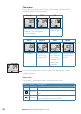
5 Specifications Technical specifications ¼¼ Note: For updated technical specifications, compliance and certifications, refer to out web sites.
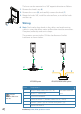
Drawings Dimension, Remotes 40 mm (1.55") 80 mm (3.15") 144 mm (5.67”) 132 mm (5.20") c/c 130 mm (5.12") 66 mm (2.60") c/c 66 mm (2.60") QS80 FU80 205 mm (8.05") 205 mm (8.05") NF80 63 mm (2.46") 51 mm (1.98") 16 mm (0.63") 63 mm (2.
Dimension, Bulkhead mounting frame c/c 130 mm (5.12") 80 mm (3.15") 144 mm (5.67”) 40 mm (1.55") c/c 66 mm (2.
*988-10199-001*