
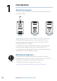
Operation Manual

4 |
Installation | FU80, NF80, QS80 User Guide
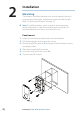
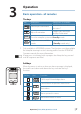
The lever can be mounted in a 180° opposite direction as follows:
1. Remove the knob’s cap (A)
2. Remove the screw (B), and carefully remove the knob (C)
3. Rotate the knob 180°, install the selected lever, re-install the knob
and the cap
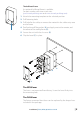
Wiring
¼ Note: Don’t make sharp bends in the cables, and avoid running
cables in a way that allows water to flow down into the connectors.
If required, make drip and service loops.
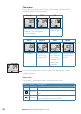
The remotes connect to the CAN bus backbone or SimNet
backbone as shown below.
A
B
CC
A
D
E
FF
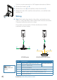
AP70/AP80 system AP24/AP28/NSE/NSS/NSO systems
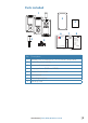
Item Component
A Micro-C drop cable. 6 m (19.7 ft)
Included with the
unit
B Micro-C T-connector
C CAN-bus backbone
D Simnet to Micro-C (female) cable. 0.5 m (1.64 ft)
E SimNet T-joiner (3p) or SimNet Multijoiner (7p)
F SimNet backbone
B
A
C
For part
numbers, refer to our
web site.
6 |