NSO-II Marine Processor Installation Manual ENGLISH simrad-yachting.
Preface As Navico is continuously improving this product, we retain the right to make changes to the product at any time which may not be reflected in this version of the manual. Please contact your nearest distributor if you require any further assistance. It is the owner’s sole responsibility to install and use the instrument and transducers in a manner that will not cause accidents, personal injury or property damage. The user of this product is solely responsible for observing safe boating practices.
user is encouraged to try to correct the interference by one or more of the following measures: Reorient or relocate the receiving antenna • Increase the separation between the equipment and receiver • Connect the equipment into an outlet on a circuit different from that of the receiver • Consult the dealer or an experienced technician for help Trademarks • • • • NMEA 2000 is a registered trademark of the National Marine Electronics Association Navionics is a registered trademark of Navionics SpA Simrad is
Contents 4 NSO-II Overview 4 5 6 Included Items NSO-II Marine Processor Box OP40 Controller (not included) 7 Hardware Installation 7 7 7 Mounting location Marine Processor Installation OP40 Installation 8 Wiring 8 8 8 10 11 11 12 14 14 15 16 Guidelines Power Connection Power Control Connection (yellow wire) External alarm Connecting displays Connecting control devices NMEA 2000 / SimNet NMEA 0183 device connection Ethernet device connection Video In CZone connection to NMEA 2000 17 Software set
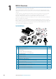
1 NSO-II Overview The NSO-II Marine Processor features a fast quad core processor, and dual monitor outputs to drive two displays with independant information. Connectivity options for data are broad, with an internal ethernet switch with three ports, NMEA 0183 transmit and receive ports, and a connection point for a NMEA 2000 compliant data bus. Insight charting is embedded for the US market, where other markets include a basemap bundled with C-MAP BDS or Navionics SD download cards.
NSO-II Marine Processor Box 1 2 3 7 Key 4 8 5 6 9 Description 1 Ethernet Network ports with PoE (2x) 2 Ethernet Network port (1x) 3 Video Input BNC sockets (2x) 4 NMEA 2000 data port 5 NMEA 0183 & RS422 (2x) 6 Power connector 7 USB ports (2x) 8 HDMI sockets (2x) 9 SD Card slot NSO-II Overview | NSO-II Installation Manual |5
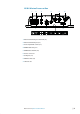
OP40 Controller (not included) 2 3 1 16 4 5 6 DISPLAY MOB PLOT MARK GO TO VESSEL 2 ABC 3 DEF 4 GHI 5 JKL 6 MNO CHART RADAR 7 PQRS 8 9 ECHO NAV STBY AUTO 0 INFO PAGES 15 WXYZ PWR 14 9 OUT IN 1 TUV 8 7 13 10 MENU 12 WIN 11 1 MOB (Man Overboard): A long press will position a Man Over Board (MOB) waypoint at the vessel’s current position 2 Display Under Command LEDs: Indicate which display the OP40 is controlling 3 DISPLAY: Short press: Change which display the OP40 is c
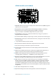
2 Hardware Installation Mounting location Choose the mounting locations carefully before you drill or cut. Be sure to leave a direct path for all of the cables. Ensure that any holes cut are in a safe position and will not weaken the boat’s structure. If in doubt, consult a qualified boat builder. Before cutting a hole in a panel, make sure that there are no hidden electrical wires or other parts behind the panel.
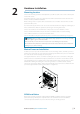
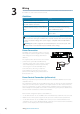
3 Wiring For easier access to connectors, undo the two philips screws visible on the bottom front of the NSO-II case, and remove the lower shroud.
Power Control unconnected Device will turn on and off when the power button on the front of the unit is pressed. Leave yellow Power Control wire disconnected. Tape or heatshrink end to prevent shorting. + _ Power Control to supply positive (auto on) Device will turn on immediately when power is applied. Common the yellow wire with the red wire after the fuse. ¼ Note: The unit can not be powered down by power button, but can be put in to standby mode. (screen backlight also turns off ).
External alarm Blue wire on power cable: An external alarm can be connected to one or more NSO-II Processors on the network. The external alarm can be a small peizo buzzer connected directly, or a horn siren connected via a relay. Alarms are configured globally in the system i.e they can be configured on any one networked multifunction device or IS40 instrument, and be seen, heard, and acknowledged from all devices.
Connecting displays Upto two displays may be connected to the NSO-II via the HDMI ports. Currently supported monitors, are the Simrad DI-15, MO-L 15/17/19, MO-16/19/24, legacy MO-19, and KEPMGB-15T. It is possible to use third party monitors, however these should conform to the supported resolution and refresh rates defined in “Specifications” on page 41. ¼ Note: LCD monitors intended for home/office use are not designed to operate in areas exposed to direct sunlight, and will appear dark and difficult to read.
Touch screen control The NSO-II may be controlled solely by touchscreen displays. Support is included to interface with the MO-16, MO-19, and MO-24, and KEPMGB-15T but other screens may also work, though no official support can be offered. The MO series monitors require RS422 communications protocol, however the ports can also be configured to output RS232 for monitors requiring this protocol. The KEP monitor control is connected via USB. Each USB port relates to one of two screens on the NSO-II.
¼ Note: Most NMEA 2000 devices can be connected directly to a Simrad SimNet backbone and SimNet devices can be connected to a NMEA 2000 network by using adapter cables. ¼ Note: Simrad devices with Micro-C NMEA 2000 connectors are fully compatible with a SimNet network by using a Micro-C to SimNet adapter cable. ¼ Note: IS40 displays have two Micro-C connectors, and can either be connected inline with the backbone, or wired individually off a drop cable.
NMEA 0183 device connection The NSO-II has four serial ports, which are connected to via two discrete cables. Each cable has one set of connections for NMEA 0183 Receive and Transmit. Both the baud rate (up to 38,400 baud) and sentences output by the NSO-II, can be configured. Refer to “NMEA 0183 supported sentences” on page 40 for a complete list of sentences.
If the number of ethernet devices exceeds the number of available ports on the NEP-2, it is possible to link two or more NEP-2 modules together to provide the required ports. The NEP-2 modules are fitted with 5 ethernet ports. ¼ Note: When designing a system, take in to account the ports ‘lost’ when used for linking multiple NEP-2 modules together. Video In Each NSO-II can be connected to two composite video cameras, and display video images on its displays. Both NTSC and PAL formats are supported.
CZone connection to NMEA 2000 When interfacing to C-ZONE network it is recommended to use a BEP Network interface bridge to join the two network backbones together. The CZONE / NMEA 2000 Network interface bridge isolates the power of the two networks, but allows data to be freely shared between both sides. C-ZONE Simrad The Network Interface has built in terminators so needs to be placed at the extremity of each network backbone.
4 Software setup Power Control setup To configure a display as a Power Control ‘Slave’ or ‘Master’, select ‘Power Control’ from the ‘Settings’ menu. The following Simrad products can be activated by a device set ett to master: NEP-2, BSM-1, BSM-2, LSS-1, LSS-2, WM-2, SonicHub, BR24/3G/4G Broadband radar, , as well as all current Simrad MFDs. Devices not controlled via a master, will need their yellow wire switched to supply positive in order to activate.
Echosounder software version For external sounder modules, the software version is displayed under Sonar installation. To upgrade Sonar software, see “Software Updates and Screen Calibration” on page 35 Water speed calibration (echosounder transducer) Water speed calibration is used to adjust the speed value from the paddle wheel to match the actual boat speed through the water. Actual speed can be determined from GPS speed over ground (SOG) or by timing the boat over a known distance.
Radar setup Setup and configuration of the Broadband radar has been simplified compared to traditional pulse radars. There is no zero range (time delay), no warm up time, and no burn-in required.. Radar status Scanner type Identifies the model of scanner connected to the network. Software version Check to make sure you have the latest software. check website for the latest version. Serial Number This number should be recorded for support and insurance purposes.
Sidelobe suppression Occasionally false target returns can occur adjacent to strong target returns such as large ships or container ports. This occurs because not all of the transmitted radar energy can be focused into a single beam by the radar antenna, a small amount energy is transmitted in other directions. This energy is referred to as sidelobe energy and occurs in all radar systems. The returns caused by sidelobes tend to appear as arcs.
Serial port setup NMEA 0183 setup is done from the Network Settings page. Receive waypoint Select this option to allow device capable of creating and exporting waypoints via NMEA 0183 to transfer directly to the NS0-2. Serial Ports This should be set according to correspond with devices connected to the NMEA 0183 input and output. Each Coomunication Port input and output (Tx, Rx) always use the same standard.
NMEA 2000 / SimNet setup • • • • • • • Setup is required on initial start up of the system, or if any part of the network has been changed or replaced.
Diagnostics The NMEA 2000 tab on the diagnostics page can provide information useful for identifying an issue with the network. Bus state simply indicates whether the bus is powered, but not necessarily connected to any data sources. However if bus shows as ‘off ’, but power is present along with an increasing error count, it is possible that termination or cable topology is incorrect. Rx Overflows: The CAN driver got too many messages for its buffer before the application could read them.
IP addresses The lower table shows the IP address of the display being viewed (top of list), the Master display (with a tick next to it), and any other displays in a multi display network. The function of the Master is invisible to the end user - It manages database synchronisation, however this task automatically shifts to another display if the current master is shut down.
Wifi setup To connect to a GoFree device a suitable wifi Android tablet or Apple ipad is required. Navigate to the wifi network connection page on the tablet, and find the ‘GoFree Wifi xxxx’ network. Connect to the network using the eight character password printed on the silver label of the GoFree module. If the module is installed out of easy access, see the following section ‘Access Points’ on how to identify the ‘Network Key’ (password) from the NSO-II.
Channel Channel setting is available in order to overcome potential interference to the GoFree device by another RF device transmitting in the same frequency band. Advanced Tools are available within the NSO-II software to assist in fault-finding and setting up the wifi network. Iperf Iperf is a commonly used network performance tool. It’s provided for testing Wifi network performance around the vessel so weak spots or problem areas can be identified.
Autopilot setup Verifying the autopilot connection When an AC12N, AC42N, or SG05 is connected to the NSO-II system, the NSO-II will automatically detect the autopilot and an Autopilot menu icon will be included in the ‘Settings’ menu. If no ‘Autopilot’ icon is available in the menu, establish the connection by running the auto select process. The auto select process may also be used if the list of data sources needs to be updated when a unit has been physically replaced.
¼ Note: Installing a feedback unit will enhance the performance of the autopilot and provide an accurate rudder angle indicator on the autopilot display. Unless impractical or impossible, a rudder feedback unit should be installed. 5. Set the drive voltage • Refer to the drive unit table in the AC12N/AC42N Installation manual or to your drive unit documentation for information. 6.
Seatrials A seatrial can only be performed if the dockside settings are completed and confirmed. The seatrial must always be performed in open waters at a safe distance from other traffic. ¼ Note: You can switch the autopilot to standby mode and take manual control of the boat at any time during the seatrial by pressing the ‘STBY/AUTO’ key.
LUBBER LINE Magnitude of local field in % of earth’s magnetic field. Direction of local field with respect to lubber line. It can also be on the reciprocal. 1. 2. 2. Find the bearing from the boat position to a visible object. Use a chart or a chart plotter Steer the boat so that the center line of the boat is aligned with the bearing line pointing towards the object Change the offset parameter so that the bearing to the object and the compass readout becomes equal.
HI-A High response parameters set automatically LO-A Low response parameters set automatically HI-M High response parameters set manually LO-M Low response parameter set manually Autotuning The autotune feature will run the boat through several tests and then automatically set the most important steering parameters. Autotune is not required for the autopilot to function, as it is preset with steering parameters that should steer most boats in the 30-50 foot range.
VMG optimizing You can optimize the VMG to wind. When selected the function will be active for 5–10 minutes after a new wind angle has been set and only when beating. Layline steering Layline steering is useful when navigating. Cross Track Error (XTE) from the navigator will keep the boat on the track line. If the XTE from the navigator exceeds 0.15 nm, the autopilot will calculate the layline and track towards the waypoint.
Minimum rudder This parameter filters small rudder commands to prevent high rudder activity. Some boats may have a tendency to not respond to small rudder commands around the “course keeping” position because of a small rudder, a rudder deadband, whirls/disturbance of the water-stream passing the rudder or it is a single nozzle water jet boat. By increasing the Minimum rudder parameter you may improve the course keeping performance on some boats. This will however increase the rudder activity.
Setting CZone to display at startup With this option selected, the CZone control page will be shown first, every time the NSO-II is powered up. CZone backlight control Enabling this will cause the NSO-II to synchronize its backlight setting with that of any CZone Display Interfaces set up to share backlight settings. Import and backup a config file The files page may be used to import CZone config files, or export a copy to a Micro SD card.
Software Updates and Screen Calibration From time to time Simrad releases software updates to its existing products. Updates are created for a variety of reasons; to add or improve features, to add support for new external devices, or to fix software bugs. Updates can be found on the Simrad website: http://www.simrad-yachting.com/Downloads/ Software-Updates/ The NSO-II may be used to apply software updates to itself, and to supported NMEA 2000 and CZone devices, with files read off an SD card.
5 Accessory cables NMEA 2000 compliant data cables Part Number Description 000-0124-69 Micro-C starter kit: 120 ohm female terminator cap 120 ohm male terminator cap Micro-C T-piece connector Micro-C 2’ (0.61M) extension cable Micro-C 15’ (4.55M) extension cable Mirco-C power cable 000-10996-001 Micro-C 4-way T-piece connector 000-0127-52 Micro-C Terminator kit (male and female caps) 000-0119-79 Micro-C T-piece connector 000-0119-75 Mirco-C power cable 000-0119-88 Micro-C 2’ (0.
6 Supported data NMEA 2000 compliant PGN List NMEA 2000 PGN (receive) 59392 59904 60928 61184 65285 65289 65291 65292 65293 65323 65325 65341 65480 126208 126992 126996 127237 127245 127250 127251 127257 127258 127488 127489 127493 127503 127504 127505 127506 127507 127508 127509 128259 128267 128275 129025 129026 129029 129033 129038 129039 129040 129283 129284 129539 ISO Acknowledgement ISO Request ISO Address Claim Parameter Request/Command Temperature with Instance Trim Tab Insect Configuration Backlig
129540 129794 129801 129802 129808 129809 129810 130074 130306 130310 130311 130312 130313 130314 130576 130577 130840 130842 130845 130850 130851 130817 130820 130831 130832 130834 130835 130838 130839 130843 38 | GNSS Sats in View AIS Class A Static and Voyage Related Data AIS Addressed Safety Related Message AIS Safety Related Broadcast Message DSC Call Information AIS Class B “CS” Static Data Report, Part A AIS Class B “CS” Static Data Report, Part B Route and WP Service - WP List - WP Name & Position
NMEA 2000 PGN (transmit) 61184 65287 65289 65290 65291 65292 65293 126208 126992 126996 127237 127250 127258 128259 128267 128275 129025 129026 129029 129283 129284 129285 129539 129540 130074 130306 130310 130311 130312 130577 130840 130845 130850 130818 130819 130828 130831 130835 130836 130837 130839 130845 130850 Parameter Request/Command Configure Temperature INSOcts Trim Tab Insect Calibration Paddle Wheel Speed Configuration Backlight Control Clear Fluid Level Warnings LGC-2000 Configuration ISO Comman
NMEA 0183 supported sentences TX / RX GPS Receive GGA GLL GSA GSV VTG ZDA Transmit GGA GLL GSA GSV VTG ZDA APB BOD BWC BWR RMC Navigation Receive RMC Transmit AAM RMB XTE Echo Receive DBT DPT MTW VLW VHW Transmit DBT DPT MTW VLW VHW HDT HDM Compass Receive HDG Transmit HDG Wind Receive MWV MWD Transmit MWV MWD AIS / DSC Receive DSC DSE VDM AIS sentences are not bridged to or from NMEA 2000.
7 Specifications Mechanical/Environmental Casing Operating temp Water ingress Weight - processor unit only Dimensions (overall) Electrical Operating voltage Power consumption Low power standby mode Protection Alarm output current Processor RAM Storage Conformity Interfaces Ethernet NMEA 2000 (compliant) Video input Video output (60Hz nominal) USB SD NMEA 0183 port baud rate RS422 port baud rate Charting support ABS plastic -15°C to +55°C IPx2 1060 grams 281 mm (W) x 232 mm (H) x 65.5 mm (D) 9 - 31.
281 mm (11.05”) 42 | 66 mm (2.58”) 265 mm (10.42”) Dimensioned drawings | NSO-II Installation Manual 130 mm (5.13”) 232 mm (9.14”) R= 2.5 (0. mm 1”) 8.0 mm R4 (0 .2 m .17 m (0.
*988-10392-001*