
Installation manual


8 |
Wiring | NSO-II Installation Manual
Wiring
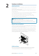
For easier access to connectors, undo the two philips screws visible on the bottom front of
the NSO-II case, and remove the lower shroud.
Guidelines
Don’t do this: Do this:
Don’t make sharp bends in the cables Do make drip and service loops
Don’t run cables in a way that allows water to
fl ow down into the connectors
Do cable tie all cables to keep them secure
Don’t route the data cables in areas adjacent
to radar, transmitter, or large current carrying
cables
Do solder/crimp and insulate all wiring
connections, if extending or shortening
power or NMEA 0183 cables
Do leave room at the back to install and
remove cables
!
Warning: Before starting the installation, be sure to turn electrical power off . If power is
left on or turned on during the installation, fi re, electrical shock, or other serious injury may
occur. Be sure that the voltage of the power supply is compatible with the NSO-II Marine
Processor.
!
Warning: The positive supply wire (red) should always be connected to (+) DC with
the supplied fuse or a circuit breaker (closest available to fuse rating).
Power Connection
The NSO-II can be powered by either 12 V or 24 V
DC. Displays are protected against reverse polarity,
under voltage and over voltage (for a limited
duration).
The supplied power cable has four cores used for:
• power into the system (Red and Black wires)
• controlling power state of the display or power
state of other displays and devices (Yellow wire)
• connecting to an external alarm (Blue wire)
Connect Red to (+) DC using a 3 amp fuse.
Connect Black to (-) DC. The processor can be
powered on and off using the power button on
the front of the case.
Power Control Connection (yellow wire)
Planning is required how you want to be able to turn on and off the NSO-II and connected
compatible devices.
The yellow Power Control wire on the NSO-II power cable can either be an input that will turn
on the processor when power is applied, or an output that turns on other devices when the
processor is powered on. It can be confi gured at the installation stage to control the power
state of displays and compatible devices. When commissioning the system, the NSO-II can be
set to be a Power Control Slave or Power Control Master.
Power Control confi guration options of the NSO-II are:-
• use the Power button on case or OP40 to turn on the NSO-II only: Yellow wire not connected
• NSO-II to turn on when power is applied to the processor: Common red and yellow wires
• use the Power button on case or OP40 to turn on the processor and other NSO-IIs and or
compatible devices such as Broadband Radar: Yellow wire connected to a Power Control Bus.
(Set one or more displays to be a Power Control Master)
3
+
_
NSO-II_IM_EN_988-10392-001.indd 8 9/07/2013 3:52:52 p.m.