
Installation manual


| 7
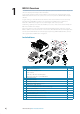
Hardware Installation | NSO-II Installation Manual
Hardware Installation
Mounting location
Choose the mounting locations carefully before you drill or cut. Be sure to leave a direct path
for all of the cables.
Ensure that any holes cut are in a safe position and will not weaken the boat’s structure. If in
doubt, consult a qualifi ed boat builder.
Before cutting a hole in a panel, make sure that there are no hidden electrical wires or other
parts behind the panel.
Do not mount any part where it can be used as a hand hold, where it might be submerged, or
where it will interfere with the operation, launching or retrieving of the boat.
Choose an area where the unit will not be subjected to excessive vibration, or heat.
Choose a location that will not expose the unit to conditions that exceed the IP rating.
Leave suffi cient clearance to connect all relevant cables.
For overall width and height requirements, please see “Dimensioned drawings” on page 42.
!
Warning: When installing, ensure appropriate safety equipment is used, e.g. ear muff s,
protective glasses, gloves and a dust mask.
Power tools may exceed safe noise levels, and can cast off dangerous protectiles.
The dust from many materials commonly used in boat construction may cause irritation or
damage to eyes, skin, and lungs.
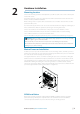
Marine Processor Installation
Hold the processor up to the desired location on the mounting surface, and with a pencil or
marker, trace the keyhole at each of the four mounting tabs. Remove the processor and mark
the centre of the narrow end (top) of each keyhole.
The supplied fasteners can be used when installing the processor to a wooden or fi breglass
bulkhead. For steel or aluminium it may be preferable to use machine screws with lock nuts.
For supplied fasteners, pre-drill the holes at the marked points with no larger than a 2.7 mm
drill bit. When drilling in to fi breglass covered in gelcoat, it is recommended to carefully
remove the gelcoat layer with a small countersink bit after the hole has been drilled. This will
prevent the gelcoat from cracking as the fastener is tightened.
= PHILLIPS #2 (PH2)
OP40 Installation
Refer to the mounting template supplied with the OP40. Installation location should be
planned keeping in mind space required for the selected monitor. Ensure the OP40 is
conveniently located within easy reach of helm seating or standing position.
2
NSO-II_IM_EN_988-10392-001.indd 7 9/07/2013 3:52:45 p.m.