SIMRAD A KONGSBERG Company SIMRAD Fixed VHF DSC Radio RD68 Service Manual
SIMRAD A KONGSBERG Company SIMRAD Fixed VHF DSC Radio RD68 Contents
CONTENTS 1 INTRODUCTION 1.1 1.2 Electronic PCBs Mechanical Components 2 OPERATION 3 ASSEMBLY INSTRUCTIONS 3.1 3.2 3.3 3.4 4 MECHANICAL ASSEMBLY DRAWINGS 4.1 4.2 4.3 4.4 5 Channel Characteristic Programming Using the Programming Software Altering NVM Data FAULT FINDING 8.1 8.2 9 Circuit Schematics Component Lists and Layouts PROGRAMMING AND CONFIGURATION 7.1 7.2 7.3 8 Receiver / Transmitter PCB Assembly Control PCB Assembly Second Receiver PCB Assembly CIRCUIT DIAGRAMS 6.1 6.
10 TECHNICAL NOTES 2
SIMRAD A KONGSBERG Company SIMRAD Fixed VHF DSC Radio RD68 Introduction
1 INTRODUCTION TO THE SIMRAD RD68 FIXED DSC VHF RADIO The Simrad RD68 is a combined VHF radio, watch-keeping receiver and Class D Digital Selective Calling (DSC) unit to facilitate routine and distress calling on VHF Channel 70.
SIMRAD A KONGSBERG Company SIMRAD Fixed VHF DSC Radio RD68 Operation
2 OPERATING THE SIMRAD DSC VHF RADIO This Service Manual only contains operating instructions for those features of the Simrad RD68 Radio that are not normally available to the end user. For details of normal operation please refer to the Simrad RD68 Instruction Manual, E03912. LCD Test Mode. The LCD test mode may be entered by holding Soft Keys 2 and 4 on power up. Depressing each key in turn will then fill the display with the appropriate characters. The radio must be turned off to exit test mode.
SIMRAD A KONGSBERG Company SIMRAD Fixed VHF DSC Radio RD68 Assembly Instructions
3 ASSEMBLY INSTRUCTIONS 3.1 RD68 Chassis Pre-Assembly The main transmitter and receiver and second receiver PCBs are a matched pair and replacement of either requires the tuning of both to be checked and adjusted as necessary. Position the PCB over the Chassis. Apply a small amount of Hellerman sleeving oil to the part of the Red and Black power and the red and blue NMEA leads inside the chassis, to provide lubrication and facilitate withdrawal from the chassis as the board is set down.
When this has been achieved fully tighten the rear module screws and then the heatsink screws at the front. Solder the tinned copper wire from the Antenna socket into the board, then fold down the 2 tags, from the Antenna socket copper washer, onto the PCB and solder both tags down to the pads. 3.2 RD68 Final Assembly Fit the Cover Seal E03117 into the top cover ensuring that the seal lays into the recess around the cover.
Offer up the front panel to the chassis and, ensuring that the seal is still correctly located, fit the front panel. Refer to drawing No.E03847 and onto each of the four No.6 x 1/2" Pan Head Screws 200005, fit a M3.5 Nyltite Washer 200253. From the rear, fit these screws through the chassis and into the front panel. Screw on the front panel, fully tightening the screws. 3.3 Fist Mic Assembly Refer to Drawing No.
for 35mm. Cut off the Blue wire flush with the outer insulation, (not used). Cut back the Red wire to 20 mm long from the end of the outer insulation, the Orange and Black wire to 30 mm and the Green and White wire to 35 mm. Strip and tin the ends. Pass the end of the cable up through the hole in the bottom of the front case, apply a small quantity of Hellerman Sleeving Oil to the cable and slide on Cable Grommet E03141.
SIMRAD A KONGSBERG Company SIMRAD Fixed VHF DSC Radio RD68 Mechanical Assembly Drawings
4 MECHANICAL ASSEMBLY DRAWINGS 4.1 4.2 4.3 4.4 4.5 4.
SIMRAD A KONGSBERG Company SIMRAD Fixed VHF DSC Radio RD68 Circuit Descriptions
5 CIRCUIT DESCRIPTIONS Introduction The SIMRAD RD68 consists of 3 PCB assemblies. The main Receiver / Transmitter PCB assembly, Navico Part No. E03866, contains all the transmitter and receiver circuitry including the synthesiser, modulator and audio power amplifiers. The control PCB assembly, Navico Part No. E03656, houses the microcontroller, user controls and interfaces, display module and ATIS detection and mute circuitry. A full Class D DSC controller is also incorporated through a V.23 modem.
through the PA filter L1 to L4. L4 of this filter, with diodes D101 and D102, forms a simple forward and reverse power detector to provide power control and transmitter status indication on the front panel display. The power control signal is fed to differential amplifier IC101 together with the reference power signal from VR100 and VR101, to set the high and low power levels. The output of this amplifier forms a regulated supply with TR113 and TR114 to supply the PA drivers TR100 and TR101.
XTAL4 L10, C214, C215 D101,102 D1,D100 D2 Noise Voltage To 2nd Rx TR2 TR1 21.
5.2 Control PCB Assembly. Refer to drawing number E03656. All the functions of the radio are controlled from this assembly by the microprocessor IC4. The microprocessor has it own clock controlled by XTAL1 running at 7.15909MHz. Reset generator IC9 ensures that the microprocessor starts up correctly and resets under low voltage conditions. The microprocessor has a data bus interface driving the front panel display module.
The audio level required for alarms is controlled by IC1d. For normal key ‘beeps’the microprocessor, IC4, generates a square wave which is filtered and reduced in level by R15, R75, C14 and C105 and then fed into the audio amplifier via PLG1. For alarm generation IC1d short circuits R75 to increase the level of signal being fed to the audio amplifier.
Mic in IC1a Mod out IC1b IC9 IC8 DSC in 7.
5.3 Second Receiver PCB Assembly Refer to drawing number E03209. The second receiver is connected to the main receiver at the power splitter L10, C215, C214 and R205. The basic circuitry is the same as the receiver section of the main receiver. L300, L301 and associated capacitors form the input bandpass section, prior to the RF amplifier TR300. A second bandpass section is formed by L302 and L303, which couple into the mixer at the source of TR301.
XTAL303 TR300 TR301 17.
SIMRAD A KONGSBERG Company SIMRAD Fixed VHF DSC Radio RD68 Circuit Diagrams
6 CIRCUIT DIAGRAMS 6.
Component Lists and Layouts Receiver / Transmitter PCB Front Assembly Detail Receiver / Transmitter PCB Assembly Detail Receiver / Transmitter PCB Rear Assembly Detail Front Panel Assembly Detail (Sht 1) ATIS Front Panel Assembly Detail Second Receiver PCB Assembly Detail Fist Mic PCB Assembly Detail Telephone Handset PCB Assembly Detail E03866(Sht 1) E03866(Sht 2) E03866(Sht 3) E03658 E03865 E03211 E03285 E03309 19
SIMRAD A KONGSBERG Company SIMRAD Fixed VHF DSC Radio RD68 Programming and Configuration
7 PROGRAMMING AND CONFIGURATION Introduction All Transmitting / Receiving characteristics of the RD68 Series radiotelephones are stored in Non Volatile Memory (NVM). The NVM of any RD68 Series radio can be programmed with new characteristics using the programming kit, Part Number PR68. The following features are available: COUNTRY Selects primary mode. NVMs with INT (International) selected for the FIRST COUNTRY flag will receive on the INT Rx frequencies.
DSC IDENTIFIER (MMSI) Stores Maritime Mobile Service Identity (MMSI) number. ATIS IDENTIFIER Stores Automatic Transmission Identification System (ATIS) Number. INITIAL SET UP The PR68 programming kit operates in conjunction with an IBM compatible PC. The programme should be copied to the 'C’ drive on the PC hard disc into a directory entitled RD68DATA If using a monochrome monitor type MODE BW80.
RD68 RADIO CONFIGURATION PROGRAM --------------------------------------------------------Using COM1 port on computer NVM Data: NOT LOADED Select option:1 - Load NVM data from Radio (Copy data from radio to PC) 2 - Load NVM data from File (Load data from programme file) 3 - View/Modify NVM data (View/change displayed data) 4 - Save NVM data to Radio (Save displayed data to radio) 5 - Save NVM data to File (Save data to new PC file) 6 - CLONE from existing Radio (Copy existing data from radio to radio) 7 -
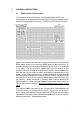
Load NVM data from Radio Connect Radio, press any key when ready Failed – check connections, is radio turned on? 00: 01: 02: 03: 04: 05: 06: 07: 08: 09: 0A: 0B: 0C: 0D: 0E: OF: 10: 11: 12: 13: 14: 15: 16: 17: 18: 19: 1A: 1B: 1C: 1D: 1E: 1F: 20: 21: 22: 23: 24: 25: 26: 27: 28: 29: 2A: 2B: 2C: 2D: 2E: 2F: 30: 31: 32: 33: 34: 35: 36: 37: 38: 39: 3A: 3B: 3C: 3D: 3E: 3F: NVM data 40: 41: 42: 43: 44: 45: 46: 47: 48: 49: 4A: 4B: 4C: 4D: 4E: 4F: 50: 51: 52: 53: 54: 55: 56: 57: 58: 59: 5A: 5B: 5C: 5D: 5E: 5F:
RD68 RADIO CONFIGURATION PROGRAM --------------------------------------------------------Using COM1 port on computer NVM Data: LOADED Software: 0.
Load NVM data from File Enter NVM Data File Name: File cannot be found or cannot be opened 00: 01: 02: 03: 04: 05: 06: 07: 08: 09: 0A: 0B: 0C: 0D: 0E: OF: 10: 11: 12: 13: 14: 15: 16: 17: 18: 19: 1A: 1B: 1C: 1D: 1E: 1F: 20: 21: 22: 23: 24: 25: 26: 27: 28: 29: 2A: 2B: 2C: 2D: 2E: 2F: 30: 31: 32: 33: 34: 35: 36: 37: 38: 39: 3A: 3B: 3C: 3D: 3E: 3F: NVM data 40: 41: 42: 43: 44: 45: 46: 47: 48: 49: 4A: 4B: 4C: 4D: 4E: 4F: 50: 51: 52: 53: 54: 55: 56: 57: 58: 59: 5A: 5B: 5C: 5D: 5E: 5F: 60: 61: 62: 63: 64: 6
View/Modify NVM data Configuration Settings Country: Second Mode Enabled: Scanning Enabled: Channel 10 Scan Enabled: Dual Watch Enabled: Tri Watch Enabled: Alternate Scan Enabled: User can disable first key beep: Startup Channel (SC): Watch Channel (WC): USA/Canada Weather Channels: DSC Identifier (MMSI): INT NO YES YES YES YES NO YES 16 16 NO ---------- ← ↑↓→ select [Pg Dn] done [Enter] modify [ESC] exit OR if radio is ATIS capable View/Modify NVM data Configuration Settings Country: Second Mode E
Save NVM data to Radio Clear Log and Directory? {Y/N} 00:1068 01:3200 02:B111 03:1101 04:0000 05:0004 06:0411 07:1111 08:1111 09:1BB3 0A:1111 0B:1110 0C:0030 0D:0004 0E:4011 OF:1111 10:1110 11:0BBB 12:3333 13:3333 14:3300 15:3333 16:3333 17:3333 18:33FF 19:5431 1A:7232 1B:0000 1C:0000 1D:0000 1E:0000 1F:0000 20:0000 21:0000 22:0000 23:0000 24:0000 25:0000 26:0000 27:0000 28:0000 29:DFD2 2A:FFFF 2B:FFFF 2C:0000 2D:0000 2E:0000 2F:0000 NVM data 30:0000 40:9876 31:0000 41:5432 32:0000 42:10FF 33:0000 43:FF
Save NVM data to File Enter Data Ident: BRITISH 00:1068 01:3200 02:B111 03:1101 04:0000 05:0004 06:0411 07:1111 08:1111 09:1BB3 0A:1111 0B:1110 0C:0030 0D:0004 0E:4011 OF:1111 10:1110 11:0BBB 12:3333 13:3333 14:3300 15:3333 16:3333 17:3333 18:33FF 19:5431 1A:7232 1B:0000 1C:0000 1D:0000 1E:0000 1F:0000 20:0000 21:0000 22:0000 23:0000 24:0000 25:0000 26:0000 27:0000 28:0000 29:DFD2 2A:FFFF 2B:FFFF 2C:0000 2D:0000 2E:0000 2F:0000 NVM data 30:0000 40:9876 31:0000 41:5432 32:0000 42:10FF 33:0000 43:FFFF 34:
Save NVM data to File Enter NVM Data Filename: C:\MY DOCUMENTS\UK.
View / Modify NVM data Normal Channel Settings 0:--01 : - - D 02 : - - D 03 : - - D 04 : - - D 05 : - - D 06 : - - S 07 : - - D 08 : - - S 09 : - - D 10 : - - D 11 : - - D 12 : - - D 13 : - - D 14 : - - D 15 : - L S 16 : - - S 17 : - L S 18 : - - D 19 : - - D 20 : - - D 21 : - - D 22 : - - D 23 : - - D 24 : - - D 25 : - - D 26 : - - D 27 : - - D 28 : - - D 29 : - - 31 : - - 37 : - - - (- - -) disabled (S) Simplex ← ↑↓→ select 60 : - - D 61 : - - D 62 : - - D 63 : - - D 64 : - - D 65 : - - D 66 : - - D 67
View / Modify NVM data Private Channel Settings Channel Attributes P0 P2 P3 P4 P5 P6 P7 P8 P9 ------------------- Frequency (MHz) 0.000 0.000 0.000 0.000 0.000 0.000 0.000 0.000 0.
SIMRAD A KONGSBERG Company SIMRAD Fixed VHF DSC Radio RD68 Fault Finding
8 FAULT FINDING 8.1 Common User Faults None Yet Identified. 8.
SIMRAD A KONGSBERG Company SIMRAD Fixed VHF DSC Radio RD68 Spare Parts Detail
9 SPARE PARTS DETAIL 9.1 Spares Packs Part No. RTPK18 RTPK18:A RTPK19 RTPK19:A RTPK20 RTPK21 Description Front Panel Assembly Front Panel Assembly ATIS Version Front Panel PCB Front Panel PCB ATIS Version Front Panel Assembly (Minus PCB) PCBs & Power Module Assembly Items common to RT1200, RT1400 and RD68 Part No. RTPK9 MB1000:BK RTPK12 RTPK13 RTPK15 THS4:SIM CRDL1:BK FTM5:SIM 9.
SIMRAD A KONGSBERG Company SIMRAD Fixed VHF DSC Radio RD68 Technical Notes
10 TECHNICAL NOTES None Yet Issued 34