
Installation Manual

6. Disconnect the display cable from the socket on
the communication assembly.
7. Use a current clamp to ensure that no current is present in the DC conductors.
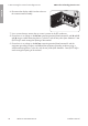
8. Ensure there is no voltage on the AC-out connecting terminal plate between L1 and N and L2
and N using a suitable measuring device. To do this, stick the test probe (max. diameter: 2mm
(0.078in)) in each rectangular opening of the terminal.
9. Ensure there is no voltage on the AC-out connecting terminal plate between L1 and the
equipment grounding conductor and L2 and the equipment grounding conductor using a
suitable measuring device. To do this, stick the test probe (max. diameter: 2mm (0.078in)) in
each rectangular opening of the terminal.
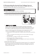
8 Disconnecting the Inverter from Voltage Sources
SMA Solar Technology America LLC
Installation manualSB5.0-6.0-1SP-US-40-IA-xx-1058
ENGLISH