User’s Guide RS232 Bluetooth Adapter Version: 2.8 SMART Modular Technologies, Inc., 4211 Starboard Drive, Fremont, CA 94538 Web: www.smartm.com Technical support: www.smartm.com/btsupport STBTIOBxXXPARSM User Guide 2.
Table of Contents 1. Introduction ……………………………………………………………………………………………………………………4 2. Products and Firmware ……………………………………………………………………………………………………...4 3. Physical Product Features …………………………………………………………………………………………………..4 3.1. ADAPTER ………………………………………………………………………………………………….……………4 4. Changing Settings ……………………………………………………………………………………………………………5 4.1. Configuration features at a glance ……………………………………………………………………………………5 4.2. Accessing the configuration menus ……………………………………………………...…………………………..5 5.
7. Connecting adapters over Bluetooth ……………………………………………………………………………………..23 7.1. Client/Server Pair: “ Cable Replacement” …………………………..…………………………………………..23 7.2. Server : Connecting TO ADAPTER from a remote Bluetooth device ..…………………………………………25 7.2.1. Configure and connect ..………………………………………………….……………………………………...25 7.2.2. Bluetooth Enable your PC …………………………………..………….……………………………………….25 7.2.3. Discover the device ………………………………………………………………………………………………26 7.2.4.
1. Introduction SMART’s RS232 Bluetooth adapters are fully embedded, stand-alone Bluetooth solutions, which will Bluetooth enable any device with an RS232 port. The adapters do not require any additional Bluetooth software. For many applications, a Bluetooth adapter used in combination with another Bluetooth product (e.g.
4. Changing Settings This device contains a comprehensive set of Bluetooth and COM port features which can be changed from an easy to use “bulletin board” type configuration menu. This section gives full details about the changes that can be made, how to make them, and the implications the changes will have on the manner in which your adapter behaves. 4.1. Configuration features at a glance Below is a quick list of the configuration options that are available from the interactive menu.
5. Configuration Menu 5.1. Navigation As a general principle, from any menu screen hitting the “Enter” key refreshes the current menu and hitting 0 returns the user to the previous menu. Menu selection is performed by pressing the number on your keyboard that corresponds to the number listed on the menu item you wish to view/configure. Reminder: The configuration menu is not available while a radio (Bluetooth) connection is established. 5.2.
5.3. Communications Parameters Selecting option 1 from the “Main Menu” menu displays the Communications settings menu. It is from this menu that all available serial port settings can be changed. The available options are detailed below. ======================================== ============== MAIN MENU =============== =============== Version 3.
5.3.2.
5.3.3. Data bits Unfortunately this setting cannot be changed. The adapter only supports the 8 data bit format. Thus there is not a configuration menu option for this setting. 5.3.4. Parity ======================================== =========== Modify COMM Settings ========== ======================================== Selecting option 2 from the “Modify COMM Settings” menu enters the Set Parity menu.
5.3.6. Handshaking Handshaking is discussed in more detail in the section entitled “Handshaking Options” as it is not an option directly available from the menu. 5.3.7.
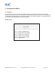
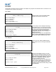
======================================== ========= Modify Bluetooth Settings =========== ======================================== Key [0] - MAIN MENU Key [1] - Set Discoverability Key [2] - Set Security Mode Key [3] - Set Encryption Key [4] - Set PIN Key [5] - Set Partner Device Key [6] - Set Client/Server Key [7] - Set Local Name Key [8] - Set Class of Device After selecting option “1” from the “Modify Bluetooth Settings” menu, the following menu is displayed.
Selecting option “2” will immediately place your ADAPTER into security mode 2. This mode allows remote Bluetooth devices to search for and retrieve the services on your ADAPTER, but will not allow them to connect unless the 2 devices are paired. Selecting option “3” will immediately place your ADAPTER into security mode 3. This is the highest security mode available. Connections of any kind from a remote Bluetooth device are only allowed after a successful “pairing” has been performed.
5.4.3. Encryption ======================================== ========= Modify Bluetooth Settings =========== ======================================== After selecting option 3 from the “Modify Bluetooth Settings” menu, the following menu is displayed.
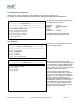
======================================== ================ Set PIN ================= ======================================== Selecting option 4 from the “Set PIN” menu will display the following menu below.
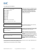
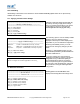
5.4.5. Partner Device This feature serves 2 purposes. In Server mode it shows the address of the last device to successfully bond and connect. In Client mode, it shows the device to which the product will attempt to pair/connect. A remote device address must first be entered into the “partner device” section before the product, configured in Client mode, will be able to initiate any connections to that remote device.
======================================== ============ Set Partner Device ============== ======================================== This expiration only deletes the Link Key created during pairing and doesn’ t remove the device itself. Key [0] - PREVIOUS MENU Key [1] - Remove partner device Key [2] – Expire pairing Selecting the option to remove the partner device as below will remove both the link key created during the pair, and it will remove the partner device itself from the memory of ADAPTER.
5.4.7. Local Device Name ======================================== ====== Modify Bluetooth Settings ======= ======================================== Key [0] - MAIN MENU Key [1] - Set Discoverability Key [2] - Set Security Mode Key [3] - Set Encryption Key [4] - Set PIN Key [5] - Set Partner Device Key [6] - Set Client/Server Key [7] - Set Local Name Key [8] - Set Class of Device In scenario’s where more than 1 ADAPTER is to be used in the same geographical location (i.e.
Enter the new local name: RS232 Test Adapter ======================================== ============ Set Local Name ============ ======================================== Press ENTER when you are satisfied with your name. The menu will now update with your chosen name selection. Key [0] - PREVIOUS MENU Key [1] - “SMBT-178 RS232 SPA1” Key [2] - “SMBT-178 RS232 SPA2” Key [3] - “SPA_1” Key [4] - “SPA_2” Key [5] - Enter your own local device name Local Device Name: RS232 Test Adapter 5.4.8.
5.5. Display Factory Settings ======================================== ============== MAIN MENU =============== =============== Version 3.02 =============== ======================================== Selecting option 3 from the “Main Menu” menu displays the following Current settings menu.
!!!!!!!!!!!!!!!!!!!!!!!!!!!!!!!!!!!!!!!!!!!!!!!!!!!!!!!!!!!!!!!!!! ! This option changes the factory settings ! ! The settings cannot be restored by the reset button ! ! Type PROCEED to apply changes ! ! Type any other character sequence to abort ! !!!!!!!!!!!!!!!!!!!!!!!!!!!!!!!!!!!!!!!!!!!!!!!!!!!!!!!!!!!!!!!!!! This is not something you really want to do unless you’re sure you have the settings as you want them and are sure you can remember them, as there is no way back from here… Entering any characte
======================================== ========= Restore Factory Settings ============ ======================================== Baud rate: 115200 (Actual: 115168) Parity: NO parity Stop Bits: 1 stop bit Local Device Name: ADAPTER BB RS232 Converter Discoverability: On Security Mode: 3 (High) Encryption: Disabled PIN Code: 1234 Partner Device: None Client/Server: Server (accepts incoming connections) Class of Device: Peripheral Be sure to take a note of, or print these settings, as you will need to ensure
5.8. Resetting ADAPTER The ADAPTER has a “reset button” located on the side of the case as shown in section 3.1 ADAPTER above. This button performs 2 different functions. a) Resets Paired Devices. A short press (less than 3 seconds) of the reset button causes any paired device information to be deleted.
With a DCE adapter or a DTE when a “gender changer/null-modem” is connected, the (Female 9 pin D Type) Pin-Outs are… Pin Signal 1 N/C 2 3 Pin Signal Pin Signal 4 DSR - N/C 7 CTS TxD 5 Ground 8 RTS RxD 6 DTR - N/C 9 Auto-detect Pwr The female connector is designed so that it can be plugged directly into a PC’s motherboard COM port. If you are connecting it directly to a different device you may need an additional cable, such as a “cross-over” or “nullmodem” cable.
======================================== ============== MAIN MENU =============== ============== Version 3.02 ================ ======================================== From the main menu select option 2 “Modify Bluetooth Settings”.
======================================== ====== Modify Bluetooth Settings ======= ======================================== Key [0] - MAIN MENU Key [1] - Set Discoverability Key [2] - Set Security Mode Key [3] - Set Encryption Key [4] - Set PIN Key [5] - Set Partner Device Key [6] - Set Client/Server Key [7] - Set Local Name Key [8] - Set Class of Device ================================== ========== Set Client/Server =========== ================================== DEVICE MUST BE REBOOTED IN ORDER TO APPLY TH
7.2.3. Discover the device Using SMART’s Bluetooth Windows software (for controlling the USB adapter) by first opening the “Bluetooth Devices” window and clicking the Search for Devices icon. This sets the software to display all the Bluetooth devices it can find “in range”. This software will not operate the adapter products if attached to the PC. Assuming that your adapter is switched on and in radio range you should see it displayed (perhaps alongside other Bluetooth devices in range) in the main screen.
9. Troubleshooting In the rare occasion that you experience difficulties using this product, please read and try any suitable suggestions from the table below before contacting our support team. Symptom Description Solution Data doesn’t seem to be received by the product, but seems to be sent by it (e.g. data only traveling in one direction) This is normally the result of the product being configured as requiring RTS/CTS handshaking, but being plugged into a device which does not support it.
10. Technical Specifications Class 2 Bluetooth Device = > 0 dBm < +4.0 dBm @ 25 oC Qualified Output Power: Receive sensitivity Single Slot = -83 dBm with 0.1% BER 10.1. Storage and Operating Environment 10.1.1. Storage Temperature: -10oC to +85oC Humidity: 8% to 95% non-condensing 10.1.2. Operational Temperature: 0oC to 70oC Humidity: 20% to 75% non-condensing 10.2. Power requirements 10.2.1.
11. Agency and Regulatory Body Approvals Bluetooth product operating in 2.4GHz band for Home and Office use. 11.1. Exposure to Radio Frequency Radiation The radiated output power of the BT RS232 DCE CLASS 2 and BT RS232 DTE CLASS 2 Bluetooth wireless radios are far below the FCC, Industry Canada and European Union radio frequency exposure limits. Nevertheless, the wireless radio shall be used in such a manner that the potential for human contact during normal operation is minimized.
11.3. Industry Canada ICES-003 Emission Compliance Statement This Class B digital apparatus meets the requirement of the Canadian Interference-Causing Equipment Regulations. Cet appareil numérique de la classe B respecte toutes les exigences du règlement sur le matériel brouiller du Canada. 11.4. European Radio Approval Information The BT RS232 DCE CLASS 2 and BT RS232 DTE CLASS 2 adapters are low power, wireless communication devices, operating in the 2.4 GHz band, intended for home or office use.