
User's Manual
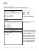
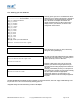
Table Of Contents

1. Introduction
SMART’s RS232 Bluetooth adapters are fully embedded, stand-alone Bluetooth solutions, which will Bluetooth enable any
device with an RS232 port. The adapters do not require any additional Bluetooth software.
For many applications, a Bluetooth adapter used in combination with another Bluetooth product (e.g. SMART’s USB adapter
connected to a PC with SMART’s BlueOpal Bluetooth Software, or a second adapter) essentially replaces the serial
cable, freeing the device from the limits imposed by the cable specification and in many applications removes the need
for expensive cable installation and maintenance. The connection uses Bluetooth security to ensure that sensitive data
is not “sniffed” by any unauthorized source, although this feature can be turned off.
The products described by this document are designed as cable replacement products. It’s primary function is to offer
“point-to-point” Bluetooth capabilities to devices which otherwise do not have the capacity for such behavior. This capability
is configured by a “set and forget” interface, which is not designed to cater for multiple device connection scenarios. At
the time of publication, the adapters are only capable of connecting to one other Bluetooth device at a time.
The adapter is user configurable at baud rates between 244 and 1.3Mbaud in steps of 244, with none, odd, or even parity,
and with 1 or 2 stop bits. Its default factory settings are 115,200 baud, no parity, 8 data bits and 1 stop bit and Hardware
Handshaking.
A convenient reset button can be used to restore various functions of the device including a restore of last saved
settings.
We trust that if you adhere to the following procedures you will enjoy many years of useful service from your SMART
RS232 Bluetooth Adapter.
2. Products and Firmware
This document covers Product Names BT RS232 DCE CLASS 2, Model ASY90178-1 and BT RS232 DTE CLASS 2
Model ASY90178-2. The Product Numbers are STBTIOBxXXPARSM, where the x represents whether the adapter is
a DCE or DTE device and the XX, which power supply is included. Any features that apply to a specific part number will be
clearly identified.
3. Physical Product Features
3.1. P/N’s STBTIOBxXXPARSM
Reset button
See “5.10 Resetting STBTIOBxXXPARSM” for details of this feature
2 LED’s – both Green
a) LED1: This is used to indicate the “Power” status of the adapter. When power is applied at the specified voltage and
current the LED turns ON.
b) LED2: Indicates transmitted/received data activity.
STBTIOBxXXPARSM User Guide 2.8 © Copyright SMART Modular Technologies 2004 Page 4 of 30