
Installation Guide


5
1. Remove the collectors from the box and allow the collectors to relax in the sun (30 minutes
to an hour). DO NOT LAY COLLECTORS ON THE GRASS IT CAN DAMAGE THE LAWN
UNDERNEATH!
2. Allow at least one foot around the solar system for brackets, piping, and working area. Roof
obstructions like vents should be taken into consideration when laying out collectors. With
a roof vent up to 3" in diameter, the collectors can be placed on either side of the vent.
WARNING: DO NOT WALK ON THE SOLAR COLLECTORS
3. Determine the position of the top collector. Lay out the mounting brackets at each slot
along the length of the collector. The collector should slope slightly toward the inlet point
(where the water enters the collectors) to allow for drainage.
4. Drill 1/8" pilot hole for lag screws provided for all brackets. Lag screws should be long
enough to reach the sub-roof under the shingles. Inject a generous amount of silicone
sealant into the holes and onto the surrounding roof surface. Mount the bracket to the roof
(as shown) with the bracket centered in the slot.
5. Remove and discard the black protective end caps covering the threaded ends of the
header pipes at both ends of the collectors.
6. Slip the black rubber connector hoses with two 1 1/2" hose clamps over the ends of
header pipes (as shown).
7. Position the hose clamps 1/2" in from each end of the rubber connector hose. Center
them over the grooves on the header and tighten.
8. Begin tying the strap to the top bracket, run through the brackets below and tie to the
bottom bracket (as shown).
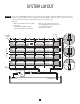
ROOF MOUNT SYSTEM INSTALLATION
Note: When completed, you will have five vertical straps running across each collector.
For high wind areas, we recommend one SK-34 High Wind Kit for each collector.
Call 1-888-560-7665 for ordering info.
DO NOT MOUNT COLLECTORS USING “C” CLAMPS ON HEADER PIPES!!
4
6
WARNING:
DO NOT ADD ADDITIONAL NON-FACTORY APPROVED MOUNTING HARDWARE.
DO NOT CLAMP HEADER PIPES DOWN.
YOU MAY DAMAGE YOUR COLLECTORS AND WILL VOID YOUR WARRANTY.
8
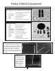
9. Install the vacuum relief end cap (provided in SK21) in the rubber hose (provided in SK21)
located at the top corner of the system (see page 4) using hose clamps (provided). Install
the rubber end cap (provided) at the diagonal bottom corner (as shown on page 4)
using a
hose clamp (provided).
10. Attach barbed end of the PVC to Hose Pipe Adapters (provided in SK21) to inlet and outlet headers using rubber hose connectors
(provided) and hose clamps (provided). Attach smooth ends of the PVC of the Hose Pipe Adapters (provided) to your feed and
return PVC pipes (as shown on page 4).
11. Inspect all clamps for proper position and tighten (DO NOT OVERTIGHTEN).
NOTE: LAYOUT PLUMBING BEFORE PRIMING AND GLUING.
12.
Run your feed and return PVC pipe from the solar to the pool equipment as shown in the diagram provided.
13. Position the 3-Way Valve (provided) in a convenient area and connect (as shown).
14.
Properly position the Check Valve (provided) between the filter and the 3-Way Valve (as shown on page 4) (with the arrow on the
Check V
alve pointing toward the 3-Way Valve). This will prevent water from flowing in the reverse direction into filter when
the pump is turned off.
15. Prime and glue all plumbing and fittings. When gluing PVC pipe, always wipe clean parts to be glued. Apply primer to parts
being joined then swath with PVC glue. Connect parts and twist quarter turn for proper bonding.
YOU ARE NOW READY TO START-UP YOUR SOLAR POOL HEATER SYSTEM!
16. Start-up your system and check for leaks.
NOTE: Upon start-up you will see air bubbles come through the return. This is normal and will stop after all the air has
been purged from the solar heating system. If not, switch the locations of the vacuum relief valve and the rubber end
cap that will eliminate the problem.