DOCSIS 3.
SMC Networks 20 Mason Irvine, CA. 92618 U.S.A. Copyright © 2011 SMC Networks All Rights Reserved Information furnished by SMC Networks, Inc. (SMC) is believed to be accurate and reliable. However, no responsibility is assumed by SMC for its use, or for any infringements of patents or other rights of third parties which may result from its use. No license is granted by implication or otherwise under any patent or patent rights of SMC.
Contents Preface..................................................................................................................... vi Key Features ..............................................................................................................vii Document Organization.............................................................................................viii Document Conventions .............................................................................................
Contents Web Management Interface Menus and Submenus ................................................. 33 System Settings Menu......................................................................................... 36 Password Settings Menu..................................................................................... 38 Remote Management Menu ................................................................................ 43 Customer UI Setup Menu ...................................................
Contents Configuring URL Blocking ........................................................................... 122 Configuring Schedule Rules ........................................................................ 124 Configuring Email and Syslog Alerts ........................................................... 125 Configuring DMZ Settings ........................................................................... 129 Using the Configuration Tools Menu .....................................................
Preface Congratulations on your purchase of the SMCD3GN3 Wireless Cable Modem Gateway. The SMCD3GN3 Wireless Cable Modem Gateway is the ideal all-in-one wired and wireless solution for the home or business environment. SMC is proud to provide you with a powerful, yet simple communication device for connecting your local area network (LAN) to the Internet. This user manual contains all the information administrators need to install and configure your new SMCD3GN3 Wireless Cable Modem Gateway.
Preface Key Features The following list summarizes the Gateway’s key features. y Integrated, CableLabs-compliant DOCSIS 1.1/ 2.0 /3.0 cable modem y Four 10/100/1000 Mbps Auto-Sensing LAN ports with Auto-MDI/MDIX y High-speed 300 Mbps IEEE 802.11n Wireless Access Point y Dynamic Host Configuration Protocol (DHCP) for dynamic IP configuration, and Domain Name System (DNS) for domain name mapping y One USB 2.0 port y IEEE 802.
Preface Document Organization This document consists of four chapters and two appendixes. y Chapter 1 - describes the contents in the Gateway package, system requirements, and an overview of the Gateway’s front and rear panels. y Chapter 2 - describes how to install the Gateway. y Chapter 3 - describes how to configure TCP/IP settings on the computer you will use to configure the Gateway. y Chapter 4 - describes how to configure the Gateway. y Appendix A - contains compliance information.
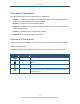
Preface Typographic Conventions This document also uses the following typographic conventions. Convention Description Bold Indicates text on a window, other than the window title, including menus, menu options, buttons, fields, and labels. Italic Indicates a variable, which is a placeholder for actual text provided by the user or system. Angled brackets (< >) are also used to indicate variables. screen/code Indicates text that is displayed on screen or entered by the user.
1 Getting to Know the Gateway Before you install the SMCD3GN3 Wireless Cable Modem Gateway, check the package contents and become familiar with the Gateway’s front and back panels.
錯誤! 尚未定義樣式。 Unpacking Package Contents The SMCD3GN3 package should include the following items: y One SMCD3GN3 Wireless Cable Modem Gateway y One power cord y One Category 5E Ethernet cable y One CD that contains this User Manual System Requirements To complete the installation, you will need the following items: y Provisioned Internet access on a cable network that supports cable modem service y A computer with a wired network adapter with TCP/IP installed y A Java-enabled Web browser, such a
錯誤! 尚未定義樣式。 Front Panel The front panel of the SMCD3GN3 Wireless Cable Modem Gateway contains a set of lightemitting diode (LED) indicators. These LEDs show the status of the Gateway and simplify troubleshooting. The front panel also contains a WPS button for configuring wireless security automatically. Figure 1 shows the front panel of the SMCD3GN3 Wireless Cable Modem Gateway. Table 1 describes the front panel LEDs. Figure 1.
錯誤! 尚未定義樣式。 Table 1. Front Panel LEDs LED POWER Color Green Description ON = power is supplied to the Gateway. OFF = power is not supplied to the Gateway. DS Green Blinking = scanning for DS channel. ON = synchronized on 1 channel only. Blue ON = synchronized with more than 1 channel (DS Bond mode). DS and US US Both DS and US blinking together = operator is performing maintenance. Green Blinking = ranging is in progress. ON = ranging is complete on 1 channel only. OFF = scanning for DS channel.
錯誤! 尚未定義樣式。 Configuring Wireless Security The front panel has a WPS button for configuring wireless security automatically. Pressing this button for 5 seconds automatically configures wireless security. If the client device supports WPS Push Button Configuration (PBC), press the button on the client within 60 seconds to automatically configure security on the client. After pressing this button for 5 seconds, the WPS LED on the front panel flashes.
錯誤! 尚未定義樣式。 Restoring Factory Defaults The Reset button on the back panel can be used to return the Gateway to its factory default settings. As a result, any changes made to the Gateway’s default settings will be lost. If you do not have physical access to the Gateway, you can use the GUI to either power cycle the Gateway (see “Using the Reboot Menu to Reboot the Gateway” on page 137) or return the Gateway to its factory default settings (see “Restoring Factory Defaults” on page 136).
2 Installing the Gateway This chapter describes how to install the SMCD3GN3 Wireless Cable Modem Gateway.
錯誤! 尚未定義樣式。 Finding a Suitable Location The SMCD3GN3 Wireless Cable Modem Gateway can be installed in any location with access to the cable network. All of the cables connect to the rear panel of the Gateway for better organization and utility. The LED indicators on the front panel are easily visible to provide users with information about network activity and status.
錯誤! 尚未定義樣式。 2. Connect the other end of the cable to your computer’s network-interface card (NIC) or to another network device (see Figure 4). Figure 4. Connecting the Gateway to the a Laptop or Desktop Computer Connecting the WAN To connect the Gateway to a Wide Area Network (WAN) interface: 3. Connect a coaxial cable to the port labeled Cable on the rear panel of the Gateway from a cable port in your home or office (see Figure 2 on page 14).
3 Configuring Your Computer for TCP/IP After you install the SMCD3GN3 Wireless Cable Modem Gateway, configure the TCP/IP settings on a computer that will be used to configure the Gateway. This chapter describes how to configure TCP/IP for various Microsoft Windows and Apple Macintosh operating systems.
錯誤! 尚未定義樣式。 Configuring Microsoft Windows 2000 Use the following procedure to configure your computer if your computer has Microsoft Windows 2000 installed. 1. On the Windows taskbar, click Start, point to Settings, and then click Control Panel. 2. In the Control Panel window, double-click the Network and Dial-up Connections icon. If the Ethernet adapter in your computer is installed correctly, the Local Area Connection icon appears. 3.
錯誤! 尚未定義樣式。 Configuring Microsoft Windows XP Use the following procedure to configure a computer running Microsoft Windows XP with the default interface. If you use the Classic interface, where the icons and menus resemble previous Windows versions, perform the procedure under “Configuring Microsoft Windows 2000” on page 20. 1. On the Windows taskbar, click Start, click Control Panel, and then click Network and Internet Connections. 2. Click the Network Connections icon. 3.
錯誤! 尚未定義樣式。 Configuring Microsoft Windows Vista Use the following procedure to configure a computer running Microsoft Windows Vista with the default interface. If you use the Classic interface, where the icons and menus resemble previous Windows versions, perform the procedure under “Configuring Microsoft Windows 2000” on page 20. 1. On the Windows taskbar, click Start, click Control Panel, and then select the Network and Internet icon. 2.
錯誤! 尚未定義樣式。 6. In the Internet Protocol Version 4 Properties dialog box, click Obtain an IP address automatically to configure your computer for DHCP (see Figure 8). Figure 8. Internet Protocol Properties Window 7. Click the OK button to save your changes and close the dialog box. 8. Click the OK button again to save your changes. Figure 9.
錯誤! 尚未定義樣式。 Configuring Microsoft Windows 7 Use the following procedure to configure a computer running Microsoft Windows 7. 1. In the Start menu search box, type: ncpa.cpl Figure 10. Typing ncpa.cpl in the Start Menu Box The Network Connections List appears. Figure 11. Example of Network Connections List 2. Right-click the Local Area Connection icon and click Properties. 3.
錯誤! 尚未定義樣式。 Figure 12. Local Area Network Connection Properties Dialog Box 4. In the properties dialog box, click Obtain an IP address automatically to configure your computer for DHCP (see Figure 13).
錯誤! 尚未定義樣式。 Figure 13. Properties Window 5. Click the OK button to save your changes and close the dialog box. 6. Click the OK button again to save your changes. Configuring an Apple® Macintosh® Computer The following procedure describes how to configure TCP/IP on an Apple Macintosh running Mac OS 10.2. If your Apple Macintosh is running Mac OS 7.x or later, the steps you perform and the screens you see may differ slightly from the following.
錯誤! 尚未定義樣式。 7. Verify that the NIC connected to the SMCD3GN3 is selected in the Show field. 8. In the Configure field on the TCP/IP tab, select Using DHCP (see Figure 14). 9. Click Apply Now to apply your settings and close the TCP/IP dialog box. Figure 14.
4 Configuring the Gateway This chapter describes how to use a Web browser to configure the Gateway.
Pre-configuration Guidelines Before you configure the Gateway, observe the guidelines in the following sections. Disabling Proxy Settings Disable proxy settings in your Web browser. Otherwise, you will not be able to view the Gateway’s Web-based configuration pages. Disabling Proxy Settings in Internet Explorer The following procedure describes how to disable proxy settings in Internet Explorer 5 and later. 1. Start Internet Explorer. 2. On your browser’s Tool menu, click Options.
錯誤! 尚未定義樣式。 Disabling Proxy Settings in Safari The following procedure describes how to disable proxy settings in Safari. 1. Start Safari. 2. Click the Safari menu and select Preferences. 3. Click the Advanced tab. 4. In the Advanced tab, click the Change Settings button. 5. Choose your location from the Location list (this is generally Automatic). 6. Select your connection method. If using a wired connection, select Built-in Ethernet. For wireless, select Airport. 7. Click the Proxies tab. 8.
錯誤! 尚未定義樣式。 Accessing the Gateway’s Web Management After configuring your computer for TCP/IP and performing the preconfiguration guidelines on the previous page, you can now easily configure the Gateway from the convenient Webbased management interface. From your Web browser (Microsoft Internet Explorer version 5.5 or later), you will log in to the interface to define system parameters, change password settings, view status windows to monitor network conditions, and control the Gateway and its ports.
錯誤! 尚未定義樣式。 Understanding the Web Management Interface Screens The left side of the management interface contains a menu bar you use to select menus for configuring the Gateway. When you click a menu, information and any configuration settings associated with the menu appear in the main area of the interface (see Figure 16). If the displayed information exceeds what can be shown in the main area, scroll bars appear to the right of the main area so you can scroll up and down through the information.
錯誤! 尚未定義樣式。 The bottom right side of the screen contains three buttons: y Help displays online help y Apply click this button to save your configuration changes to the displayed page y Cancel click this button to discard any configuration changes made to the current page Web Management Interface Menus and Submenus Table 3 describes the menus and submenus in the Web management interface. Note: Some menus and submenus described in this chapter may not apply to your Gateway.
錯誤! 尚未定義樣式。 QoS > COS • Defining four queues to which the Class of Service (CoS) is mapped. 65 QoS > DSCP • Defining the QoS class queue to which the customized DSCP is mapped. 67 QoS > Queue • Specifying whether QoS behavior runs with strict or weighted priority. 69 QoS > DSCP Remarking • Defining the DSCP remarking action and mode. 71 Routing Lets you set up routing tables manually and automatically using the Routing Information Protocol (RIP).
錯誤! 尚未定義樣式。 NAT Allows multiple users at your local site to access the Internet using a single pubic IP address. The submenus let you: NAT > Port Forwarding • Configure predefined and custom port forwarding settings to let Internet users 95 access local services such as the Web Server or FTP server at your local site. NAT > 1-to-1 Mapping • Perform 1-to-1 mapping between global IP addresses on the cable modem WAN 102 interface and the private IP address on the LAN.
錯誤! 尚未定義樣式。 System Settings Menu The System Settings menu lets you: y Enable or disable all commercial Gateway functions y Define the Gateway’s name and enable it for command line prompt y Enable or disable UPnP and HNAP To access the System Settings menu, click System in the menu bar. Figure 18 shows an example of the menu and Table 4 describes the setting you can select. Figure 18.
錯誤! 尚未定義樣式。 Table 4. System Settings Menu Option Option Disable All Commercial Gateway Functions Description Enables or disables all commercial Gateway functions. • Checked = all commercial Gateway functions are disabled. • Unchecked = all commercial Gateway functions are enabled. (default) Router Name The name you want to assign to the Gateway. Assign a name so that this device will not be confused with other devices on your wireless network.
錯誤! 尚未定義樣式。 Password Settings Menu The Password Settings menu lets you change the Gateway’s default administrator username and password and the user’s password. The Password Settings menu also lets you change the number of minutes of inactivity that can occur before your Web management session times out automatically. The default setting is 10 minutes.
錯誤! 尚未定義樣式。 39 SMCD3GN2 Wireless Cable Modem Gateway Administrator Manual
錯誤! 尚未定義樣式。 Figure 19.
錯誤! 尚未定義樣式。 Table 5. Password Settings Menu Options Option Description Current Password Enter the current case-sensitive administrator password. For security purposes, every typed character appears as a dot (y). The default password is not shown for security purposes. MSO Username Enter the current new case-sensitive administrator username. New Password Enter the new case-sensitive administrator password you want to use. A password can contain up to 32 alphanumeric characters.
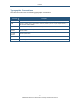
錯誤! 尚未定義樣式。 Option TACACS+ Authentication Description To enable TACACS+ authentication, check this box and then select the options for the primary and secondary authentication servers: • IP address of the TACACS+ servers. • Port number that TACACS+ uses for authentication. Default is 49. • Authentication algorithm used for authentication. Choices are ASCII, PAP, and CHAP. Default is ASCII for the primary server and ASCII for the secondary server. • Secret shared between the Gateway and TACACS+ servers.
錯誤! 尚未定義樣式。 Remote Management Menu Administrative users can use the Gateway’s Web-based management or Telnet to manage the device remotely using the public Internet.
錯誤! 尚未定義樣式。 Table 6. Remote Management Settings Menu Options Option Description WAN IP Address IP address used to access the Gateway’s Web management interface via the Internet. For example, if the WAN IP address is 123.45.67.8 and the Web management port is 8080, remote users type http://123.45.67.8:8080 to access the Web management interface. To change the value shown, check the box to the right of this option and enter a new value.
錯誤! 尚未定義樣式。 45 SMCD3GN2 Wireless Cable Modem Gateway Administrator Manual
錯誤! 尚未定義樣式。 Figure 21. Customer UI Setup Menu WAN Settings Menu The Gateway can connect to the cable service provider using either a static IP address or an IP address automatically assigned by a Dynamic Host Configuration protocol (DHCP) server. Using the WAN Settings menu, you can assign your own static WAN IP and DNS addresses to the Gateway. By default, both options are disabled, allowing the Gateway to obtain these settings automatically from a DHCP server.
錯誤! 尚未定義樣式。 Figure 22.
錯誤! 尚未定義樣式。 Table 7. WAN Settings Menu Options Option Description Do you want to assign your own WAN IP address? By default, this option is set to No. Cable modem providers typically use dynamic assignment of IP addresses. To assign a static WAN IP address to the Gateway and make the WAN fields below this option available, click Yes. Use public LAN IP as the WAN IP Check this box if you want to use the static public LAN IP address for the WAN IP address.
錯誤! 尚未定義樣式。 MAC Spoofing Menu If you need to re-register your MAC address, you can use the MAC Spoofing menu to clone (or “spoof”) the Gateway’s registered MAC address as necessary. If you use the public static LAN IP address as the WAN IP for NAT translation, no MAC spoofing is necessary, To access the MAC Spoofing menu, click WAN in the menu bar and then click the MAC Spoofing submenu. Figure 23 shows an example of the menu and Table 8 describes the settings you can select. Figure 23.
錯誤! 尚未定義樣式。 LAN Settings Menu IP addresses are close to being used up and thus very hard to get. One solution to this problem is "private" IP addresses. Private IP addresses are ranges of IP addresses set aside expressly for use by a company or other entity internally. Private IP addresses are non-routable and, therefore, cannot be used to connect directly to the Internet.
錯誤! 尚未定義樣式。 Figure 24.
錯誤! 尚未定義樣式。 Table 9. LAN Settings Menu Options Option Description Pubic LAN IP IP Address IP address of the Gateway’s private LAN settings. Default IP address is 192.168.0.1. if you change this setting, the Gateway reboots after displaying a message. IP Subnet Mask Subnet mask of the Gateway’s private LAN settings. Default subnet mask is 255.255.255.0. Domain Name Domain name of the Gateway’s private LAN settings.
錯誤! 尚未定義樣式。 Ether Switch Port Control Menu By default, the Gateway LAN ports are enabled to auto-negotiate the highest supported speed and appropriate duplex mode. If these settings prevent the Gateway from successfully connecting with other devices, you can use the Ether Switch Port Control menu to configure the Gateway to use fixed speed and duplex settings. The Ether Switch Port Control menu also let you disable the individual LAN ports.
錯誤! 尚未定義樣式。 The following procedure describes how to change the settings in the Ether Switch Port Control menu. 1. To change a port from auto-negotiation to a fixed speed and duplex setting: a. Uncheck the Auto check box for the port. b. Under Speed (10/100/1000), click the radio that corresponds to the fixed speed you want to use for that port. c. Under the Mode H/F column, leave the check mark for full-duplex mode or uncheck it for half-duplex mode. 2.
錯誤! 尚未定義樣式。 Figure 26.
錯誤! 尚未定義樣式。 Controlling LAN Access By default, All EtherLAN LAN stations is selected at the top of the menu. This setting allows all client stations to access the Internet through the Gateway. To restrict LAN access, click one of the following radio buttons and click Apply: y Trusted PC List = restricts Internet access through the Gateway to client stations in the Lan Trusted Table. To add client station to this table, see “Adding and Deleting Trusted Client Stations”, below.
錯誤! 尚未定義樣式。 4. To delete client stations from the Lan Trusted Table, click the radio button corresponding to the client station you want to delete and click the Delete button. A precautionary message does not appear before deleting a client station. 5. To enforce this policy, click Trusted PC list at the top of the menu. 6. When you finish, click Apply.
錯誤! 尚未定義樣式。 Additional Public Lan Menu Using the Additional Public Lan menu, you can add more than one public subnet to the LAN interface. To access the Additional Public Lan menu, click LAN in the menu bar and then click the Additional Public Lan submenu in the menu bar. Figure 27 shows an example of the menu. Figure 27.
錯誤! 尚未定義樣式。 Adding Public Subnets Using the following procedure, you can add up to 5 public subnets to the LAN interface. 1. In the Additional Pubic LAN menu, click the Add button The Adding Public Lan menu in Figure 28 appears. Figure 28. Adding Public Lan Menu 2. In the IP Address row, enter the IP address for the new public subnet. 3. In the Subnet Mask row, add the subnet mask for the new public subnet. 4. Click Apply to add the IP address and subnet.
錯誤! 尚未定義樣式。 8. To change the settings for a subnet, click the radio button to the left of the subnet you want to change and click the Edit button. When the Adding Public Lan menu appears, edit the IP address and subnet mask as necessary and click Apply. Click Apply in the Additional Public Lan menu to save your settings. 9. To delete a subnet, click the radio button to the left of the subnet you want to delete and click the Delete button. No precautionary message appears before you delete a subnet.
錯誤! 尚未定義樣式。 Table 10. Public IP Access Control Menu Options Option Description Enable Public IP Access Control Check this check box to make the fields on this page available. Single Address / Address Range From the first drop-down list, select whether you want to block a single IP address or a range of IP addresses. • If you select Single Address, type the four octets of the IP address you want to block. The second set of four fields in unavailable.
錯誤! 尚未定義樣式。 QoS Settings Menu Quality of Service (QoS) refers to a collection of techniques for identifying data whose delivery across the network is time sensitive, and managing its delivery through both bandwidth allocation and prioritization schemes Using the QoS Settings menu, you can enable the Gateway’s QoS module to provide guarantees on the ability of the network to deliver predictable results. To access the QoS menu, click QOS in the menu bar. Figure 30 shows an example of the menu.
錯誤! 尚未定義樣式。 Figure 30.
錯誤! 尚未定義樣式。 Port Based QoS Menu The Port Based QoS menu lets you prioritize performance of the four Gateway LAN ports. To access the Port Based QoS menu, click QOS in the menu bar and then click the Port submenu in the menu bar. Figure 31 shows an example of the menu. Note: The Port submenu is not available in the menu bar if Enable QOS Module is not checked in the QoS Settings menu (see page 62). Figure 31. Port Based QoS Menu To define port-based QoS settings: 1. Check Enable Port Based QOS. 2.
錯誤! 尚未定義樣式。 CoS Settings Menu Given that there will always be points in the network where multiple traffic streams merge or where network links will change speed and capacity, it is important to move traffic on the basis of relative importance. Without CoS prioritization, less important traffic can consume network bandwidth and slow down or halt the delivery of more important traffic.
錯誤! 尚未定義樣式。 Figure 32. CoS Settings Menu To define CoS settings: 1. Check Enable QoS Class based on CoS. 2. For each class of service, assign a queue number from 0 to 3. Higher priority values are evaluated as being of higher importance than lower priority values. 3. Under Port Default CoS, map the Gateway’s four ports to the classes of service you defined in the previous step. y CoS setting from 0 to 3 = normal priority. Packets in this queue leave the port after the high-priority queue is emptied.
錯誤! 尚未定義樣式。 DSCP Based QoS Menu The DSCP Based QoS menu lets you classify and prioritize traffic using DSCP tags. DSCP allows the Gateway to determine how traffic classes should be prioritized. Using the DSCP Based QoS menu, you can use DSCP to provide different levels of service to conforming and non-conforming traffic by appropriately selecting the DSCP values in this menu. The Gateway uses the Hierarchical Token Bucket queuing algorithm, which divides the 64 possible DSCP code values into 8 queues.
錯誤! 尚未定義樣式。 Figure 33. DSCP Based QoS Menu To define DSCP-based QoS settings: 1. Check Enable DSCP Based QoS. 2. For each index, select a DSCP value from 0 to 63. 3. Under Queue, select a queue (from 0 to 3) you want to map to this DSCP value. Higher priority values are evaluated as being of higher importance than lower priority values. 4. To define DSCP-based QoS values for other queues, repeat steps 2 and 3. 5. Click Apply.
錯誤! 尚未定義樣式。 Queue Settings Menu The Queue Settings menu lets you configure QoS behavior as either strict priority or weighted priority. y Strict priority – allows delay-sensitive data such as voice to be sent before packets in other queues. y Weighted priority – lets you assign each queue with a certain weight indicating the amount of guaranteed capacity, with high priority packets served before any low priority packets.
錯誤! 尚未定義樣式。 By default, the Gateway uses strict priority. To change to weighted priority: 1. For Queue Type, select Weighted Priority. The options in Figure 35 appear. Figure 35. Weighted Priority Options 2. For Weight Base, select a queue weight to ensure that some sets of queues get higher thresholds than others. Queue weight directs the Gateway to set the queue thresholds proportionately. Choices are 8 or 10. Queues with a weight of 10 are longer than those with a queue weight of 8. 3.
錯誤! 尚未定義樣式。 DSCP Remarking Menu The DSCP Remarking menu lets you configure the Gateway’s DSCP remarking mode and actions. To access the Queue Settings menu, click QOS in the menu bar and then click the DSCP Remarking submenu in the menu bar. Figure 36 shows an example of the menu. Note: The DSCP Remarking submenu is not available in the menu bar if Enable QOS Module is not checked in the QoS Settings menu (see page 62). Figure 36.
錯誤! 尚未定義樣式。 To configure DSCP remarking settings: 1. Check Enable DSCP Remarking. 2. Complete the options in the menu and refer to Table 12. 3. When you finish, click Apply. Table 12. DSCP Remarking Options Option Dscp remarking mode Description Lets you select the DSCP remarking mode that the Gateway is to use. Choices are: • Map frame priority to AF code points = select this option for Quality of Service configurations that use assured forwarding (AF) code points to mark packets.
錯誤! 尚未定義樣式。 Routing Menus The Routing menu provides the following submenus for configuring Gateway routing: y Static routes – lets you manually add static routes to create specific paths to desired destinations. See page 73. y RIP control – lets you select how the Gateway adjusts to physical changes in the network’s layout and exchange routing tables with other routers. See page 75. y OSPF control – lets you control how the Gateway works with the OSPF protocol. See page 79.
錯誤! 尚未定義樣式。 Using the Static Routes menu, you can add up to eight static routes, containing different networks and subnets, to routers connected to the Gateway. The following example describes how to configure a static route For example, assume that a router called SMC is connected to the Gateway with subnet address 111.222.33.0 attached to it. Also, assume that the router’s IP address in the Gateway subnet is 192.168.100.33.
錯誤! 尚未定義樣式。 6. To delete a static route, click the radio button to the left of the static route you want to delete and click the Delete button. No precautionary message appears before you delete a static route. Table 13. Add Static Routes Menu Options Option Description Name Name used to identify the route. Destination IP IP address of the destination network. Subnet Mask Subnet mask of the destination network.
錯誤! 尚未定義樣式。 Figure 39.
錯誤! 尚未定義樣式。 Table 14. RIP Control Menu Options Option Description WPS Summary Interface Name RIP Send Version Select the name of the interface. Choices are • Cable (default) • CPE Select the format and the broadcasting method of the RIP packets that the Gateway sends. Choices are: • Do Not Send (default) • RIP1 • RIP2 • RIP1/2 Your selection should match the version supported by other routers on your network.
錯誤! 尚未定義樣式。 Neighbor Enter the IP address of the Gateway’s RIP neighbor router.
錯誤! 尚未定義樣式。 OSPF Control Menu OSPF is a router protocol used in larger autonomous system networks in preference to RIP, an older routing protocol that is installed in many of today's corporate networks. Using OSPF, a host that obtains a change to a routing table or detects a change in the network immediately multicasts the information to all other hosts in the network, so that all have the same routing table information.
錯誤! 尚未定義樣式。 Table 15. OSPF Control Menu Options Option Description Interface Name A read-only field that shows the name of the interface. OSPF Status Enables or disables OSPF. • ENABLE = OSPF is enabled and the remaining fields on this menu, except Interface Name, become available. • DISABLE = OSPF is disabled. (default) Network Type The type of network on which OSPF will be used if OSPF is enabled. Choices are: • Broadcast = broadcast network. (default) • Not Broadcast = not broadcast network.
錯誤! 尚未定義樣式。 Adding OSPF Areas to the Cable Interface To add OSPF areas to the cable interface: 1. In the OSPF Control menu, be sure OSPF Status is set to ENABLE. Otherwise, you will not be able to add OSPF areas to the cable interface. 2. Click the Add button below the Additional OSPF area Table. The Adding OSPF Area menu appears (see Figure 41). 3. Complete the fields in the Adding OSPF Area menu (see Table 16). 4. Click Apply.
錯誤! 尚未定義樣式。 Figure 41. Adding OSPF Area Menu Table 16. Adding OSPF Area Menu Options Option Description Area ID Area ID associated with the OSPF interface. IP Address IP address associated with the OSPF interface. Subnet Mask Subnet mask associated with the OSPF interface. Default Cost for Area Cost for sending a packet on the OSPF interface.
錯誤! 尚未定義樣式。 Wireless Basic Settings Menu The Wireless Basic Settings menu lets you configure basic wireless settings, such as: y Enabling or disabling the Gateway’s wireless operation y Selecting a wireless mode y Configuring primary and multiple SSIDs y Configuring channel settings To access the Wireless Basic Settings menu, click Wireless in the menu bar. Figure 42 shows an example of the menu and Table 17 describes the settings you can select. Figure 42.
錯誤! 尚未定義樣式。 Table 17. Wireless Basic Settings Menu Options Option Wireless ON/OFF Description Enables or disables the Gateway’s wireless operation. • ENABLE = Gateway’s wireless operation is active. Selecting this option activates the options in this menu. Clicking Apply displays the submenus below the Wireless menu. • DISABLE = Gateway’s wireless operation is not active. Selecting this option deactivates the options in this menu. Clicking Apply hides the submenus below the Wireless menu.
錯誤! 尚未定義樣式。 Wireless Encryption Settings Menu Using the Wireless Encryption Settings menu, you can protect the data transmitted across your wireless network. The same encryption keys you specify here must also be configured on your other wireless client devices on your wireless network. To access the Wireless Encryption Settings menu, click Wireless in the menu bar and then click the Encryption submenu. Figure 43 shows an example of the menu and Table 18 describes the settings you can select.
錯誤! 尚未定義樣式。 Table 18. Wireless Encryption Settings Menu Options Option Description SSID Network name of the primary wireless carrier. This field can be changed by administrators, but not by users. Security Mode Selects the security mode used to protect transmissions across the wireless network. • None = no security is used over the wireless network. • WEP = Wired Equivalency Privacy encryption is used over the wireless network.
錯誤! 尚未定義樣式。 Figure 44.
錯誤! 尚未定義樣式。 Table 19. WEP Options Option Description WEP Key Length Level of WEP encryption applied to all WEP keys. Choices are 64-bit (10 hex digits) and 128-bit (26 hex digits). WEP Key 1 – WEP Key 4 Fields for entering up to four WEP keys manually. Alternatively, you can click the Generate Keys button to generate these keys automatically. Default WEP Key Specifies which of the four WEP keys the Gateway is to use as its default. Authentication Authentication used.
錯誤! 尚未定義樣式。 Table 20. WPA_Personal Options Option Description WPA Mode Lets administrators select the WPA mode they want to use. Choices are: • WPA-PSK = select this setting if your access points and wireless clients support WPA-Pre-Shared Key (PSK) Authentication. • WPA2-PSK = select this setting if your access points and wireless clients support WPA2-PSK Authentication. • Auto (WPA-PSK or PWA2-PSK) = select this setting if your access points and wireless clients support either WPA-PSK or WPA2-PSK.
錯誤! 尚未定義樣式。 y If your wireless devices do not support WPS, it can be hard to join a network that was set up with WPS because the wireless network name and security key are random sequences of letters and numbers. To access the WPS Setup menu, click Wireless in the menu bar and then click the WPS submenu. Figure 46 shows an example of the menu. Using the WPS Config drop-down list, select the appropriate option to enable or disable WPS setup. Figure 46.
錯誤! 尚未定義樣式。 By default, WPS is disabled. If you select ENABLE and click Apply, the options in Figure 47 are displayed. Table 21 describes the options shown. Figure 47.
錯誤! 尚未定義樣式。 Table 21. WPS Summary and WPS Progress Options Option WPS Config Description Enables or disables the Gateway’s WPS setup. • ENABLE = Gateway’s WPS setup is available. (default) • DISABLE = Gateway’s WPS setup is unavailable. WPS Summary WPS Current Status A read-only field that shows whether WPS is currently being used. WPS Configured A read-only field that whether WPS has been configured. AP PIN A read-only field that shows the personal identification number (PIN) for the access point.
錯誤! 尚未定義樣式。 MAC Filtering The MAC Filtering menu allows wireless client stations to connect over a wireless connection in two ways: y By allowing all wireless station access. y By allowing only trusted PCs. To access the MAC Filtering menu, click Wireless in the menu bar and then click the MAC Filtering submenu. Figure 48 shows an example of the menu and Table 22 describes the settings you can select.
錯誤! 尚未定義樣式。 Figure 48.
錯誤! 尚未定義樣式。 Table 22. MAC Filtering Options Option Description SSID Network name of the primary wireless carrier. MAC Filtering Mode Determines which wireless client stations can connect to the Gateway. The choices are: • Allow- All = all wireless client stations can connect to the Gateway. (default) • Allow = allow only the wireless client stations in the MAC filter table to connect to the Gateway. • Deny = no wireless client stations can connect to the Gateway.
錯誤! 尚未定義樣式。 Advanced Wireless Settings Menu Using the Advanced Wireless Settings Filtering menu, you can configure advanced wireless settings for the Gateway. To access the Advanced Wireless Settings menu, click Wireless in the menu bar and then click the Advanced Wireless Settings submenu. Figure 49 shows an example of the menu and Table 23 describes the settings you can select.
錯誤! 尚未定義樣式。 Figure 49.
錯誤! 尚未定義樣式。 Table 23. Wireless Advanced Settings Options Option BG Protection Mode Description This mode is a protection mechanism that prevents collisions among 802.11b/g modes. Choices are: • Auto = BG protection mode goes on or off automatically as needed. • Always-On = BG protection mode is always on. • Always-Off = BG protection mode is always off. (default) IGMP Snooping Enables or disables the Gateway from forwarding multicast traffic intelligently.
錯誤! 尚未定義樣式。 NAT Settings Using the NAT Settings menu, you can enable the Gateway’s Network Address Translation (NAT) table and allow multiple users at your local site to access the Internet. To access the NAT Settings menu, click NAT in the menu bar. Figure 50 shows an example of the menu. By default, the Gateway’s NAT module is enabled. To disable it, uncheck Enable NAT Module and click Apply. To enable it, check Enable NAT Module and click Apply.
錯誤! 尚未定義樣式。 Port Forwarding Menu The Port Forwarding menu lets you configure the Gateway to provide port-forwarding services that let Internet users access predefined services such as HTTP (80), FTP (20/21), and AIM/ICQ (5190) as well as custom-defined services. You perform port forwarding by redirecting the WAN IP address and the service port to the local IP address and service port. You can configure a maximum of 100 predefined and custom-defined services.
錯誤! 尚未定義樣式。 Adding Predefined Services Using the following procedure, you can select well-known services and specify the LAN host IP address(es) that will provide the service to the Internet. 1. In the Port Forwarding menu, be sure Disable Port Forwarding Function is not checked (unchecked is the default setting). 2. Click the Add button below the Predefined Service Table. The Predefined Service menu appears (see Figure 52). 3. Complete the fields in the Predefined Service menu (see Table 24). 4.
錯誤! 尚未定義樣式。 Figure 52. Predefined Service Menu Table 24. Predefined Service Menu Options Option Description Service List of predefined services from which you can choose. LAN Server IP IP address of the LAN PC or server that is running the service. Remote IPs Forwards the service to any remote IP address, one remote IP address, or a range of remote IP addresses. • If you select one remote IP address, enter the IP address in the Start IP field.
錯誤! 尚未定義樣式。 Adding Customer-Defined Services Using the following procedure, you can define special application services you want to provide to the Internet. The following example shows how to set port forwarding for a Web server on an Internet connection, where port 80 is blocked from the WAN side, but port 8000 is available. Name: Type: LAN Server IP: Remote IPs: Public Port: Private Port: Web Server TCP 192.168.0.
錯誤! 尚未定義樣式。 Figure 53.
錯誤! 尚未定義樣式。 Table 25. Customer Defined Service Page Options Option Description Name Name for identifying the custom service. The name is for reference purposes only. Type The type of protocol. Choices are TCP, UDP, and TCP/UDP. Default is TCP. LAN Server IP IP address of the LAN PC or server that is running the service. Remote IPs Forwards the service to any remote IP address, one remote IP address, or a range of remote IP addresses.
錯誤! 尚未定義樣式。 1-to-1 Mapping Menu Using the 1-to-1 Mapping menu, you can use the NAT to perform 1-to-1 mapping between global IP addresses on the cable modem WAN interface and the private IP address on the LAN. To access the 1-to-1 Mapping menu, click NAT in the menu bar and then click the 1-to1 Mapping submenu. Figure 54 shows an example of the menu. By default, 1-to-1 mapping is disabled. To enable it, uncheck Disable NAT 1-to-1 Mapping Function and click Apply.
錯誤! 尚未定義樣式。 Figure 54. 1-to-1 Mapping Menu If you enable (uncheck) NAT 1-to-1 mapping, use the following procedure to define the mapping between global IP addresses on the cable modem WAN interface and the private IP address on the LAN. 1. In the 1-to-1 Mapping menu, uncheck Disable NAT 1-to-1 Mapping Function if it is selected. 2. Click the Add button below 1-to-1 Mapping Table. The Adding NAT 1-to-1 Mapping Entry menu appears (see Figure 55). 3.
錯誤! 尚未定義樣式。 menu appears, edit the settings as necessary (see Table 26) and click Apply. Click Apply in the 1-to-1 Mapping menu to save your settings. 7. To delete a mapping, click the radio button to the left of the mapping you want to delete and click the Delete button. No precautionary message appears before you delete a mapping. 8. Click Apply in the 1-to-1 Mapping menu to save your settings. Figure 55. Adding NAT 1-to-1 Mapping Entry Table 26.
錯誤! 尚未定義樣式。 Security Settings (Firewall) Menu The Security Settings (Firewall) menu lets you enable or disable the Gateway’s firewall.
錯誤! 尚未定義樣式。 By default, the Gateway’s firewall settings are enabled. To disable the firewall, uncheck Enable Firewall Module and click Apply. Disabling the firewall hides the submenus below the Firewall menu. The Security Settings (Firewall) menu also provides an option for enabling or disabling the Session Initiation Protocol (SIP) application-layer gateway service on the Gateway firewall. This option allows SIP signaling requests to traverse directly through the Gateway to the destination device.
錯誤! 尚未定義樣式。 Configuring Access Control The Access Control menu lets you enable access control to block traffic at the Gateway's LAN interfaces from accessing the Internet. To access the Access Control menu, click Firewall in the menu bar and then click the Access Control submenu in the menu bar. Note: The Access Control submenu is not available in the menu bar if Enable Firewall Module is disabled in the Security Settings (Firewall) menu (see page 105).
錯誤! 尚未定義樣式。 Adding Predefined Access Rules Using the following procedure, you can select a well-known service and specify whether to block all LAN hosts, a single LAN host, or a range of LAN hosts. 1. In the Access Control menu, check Enable Access Control if it is not checked and click the Apply button. The remaining fields in the menu become available. 2. Under Predefined Service Table, click the Add button. The Predefined Access Rules menu appears (see Figure 58). 3.
錯誤! 尚未定義樣式。 Figure 58.
錯誤! 尚未定義樣式。 Table 27. Predefined Access Rules Menu Options Option Description Service List of predefined services from which you can choose. Remote IPs Allows access to any remote IP address, one remote IP address, or a range of remote IP addresses. • If you select one remote IP address, enter the IP address in the Start IP field. • If you select a range of remote IP addresses, enter the starting IP address in the Start IP field and the ending IP address in the End IP field.
錯誤! 尚未定義樣式。 Adding Customer-Defined Access Rules Using the following procedure, you can define your own rules regarding the type of traffic allowed from the Internet to the public LAN site. 1. In the Access Control menu, check Enable Access Control if it is not checked and click the Apply button. The remaining fields in the menu become available. 2. Under Customer Defined Service Table, click the Add button. The Customer Defined Access Rules menu appears (see Figure 59). 3.
錯誤! 尚未定義樣式。 Figure 59.
錯誤! 尚未定義樣式。 Table 28. Customer Defined Access Rules Menu Options Option Description Name Name for identifying the custom service. The name is for reference purposes only. Type The type of protocol you want to access rule. Choices are TCP, UDP, and TCP/UDP. Default is TCP. Remote IPs Lets you apply the access rule to any remote IP addresses, a single remote IP address, or a range of remote IP addresses. • If you select one remote IP address, enter the IP address in the Start IP field.
錯誤! 尚未定義樣式。 Adding Predefined Filters Using the following procedure, you can add predefined filters that block certain types of traffic from the LAN side of the Gateway to the Internet side of the Gateway . 1. In the Access Control menu, check Enable Access Control if it is not checked and click the Apply button. The remaining fields in the menu become available. 2. Under Predefined Filtering Table, click the Add button. The Predefined Filter menu appears (see Figure 60). 3.
錯誤! 尚未定義樣式。 Figure 60. Predefined Filter Menu Table 29. Predefined Filter Menu Options Option Description Service List of predefined services from which you can choose. LAN IPs Lets you apply the filter to any LAN IP addresses, a single LAN IP address, or a range of LAN IP addresses. • If you select one LAN IP address, enter the IP address in the Start IP field.
錯誤! 尚未定義樣式。 Adding Customer-Defined Filters Using the following procedure, you can add customer-defined filters that block certain types of traffic from the LAN side of the Gateway to the Internet side of the Gateway. 1. In the Access Control menu, check Enable Access Control if it is not checked and click the Apply button. The remaining fields in the menu become available. 2. Under Customer Defined Filtering Table, click the Add button. The Customer Defined Filter menu appears (see Figure 61). 3.
錯誤! 尚未定義樣式。 Figure 61.
錯誤! 尚未定義樣式。 Table 30. Customer Defined Filter Menu Options Option Description Name Name for identifying the custom service. The name is for reference purposes only. Type The type of protocol you want to filter. Choices are TCP, UDP, and TCP/UDP. Default is TCP. LAN IPs Lets you apply the filter to any LAN IP addresses, a single LAN IP address, or a range of LAN IP addresses. • If you select one LAN IP address, enter the IP address in the Start IP field.
錯誤! 尚未定義樣式。 Configuring Special Applications Using the Special Application menu, you can configure the Gateway to detect port triggers for detect multiple-session applications and allow them to pass the firewall. For special applications, besides the initial communication session, there are multiple related sessions created during the protocol communications. Normally, a normal treats the triggered sessions as independent sessions and blocks them.
錯誤! 尚未定義樣式。 Figure 62. Special Application Menu To enable port triggering: 1. In the Special Application menu, check Enable Triggering if it is unchecked and click the Apply button. The Trigger Table becomes available. 2. Click the Add button below Trigger Table. The Trigger menu appears (see Figure 63). 3. Complete the fields in fields Trigger menu (see Table 31). 4. Click Apply. (Or click Back to return to the Trigger menu or Cancel to cancel any selections you made.
錯誤! 尚未定義樣式。 Figure 63. Trigger Menu Table 31. Trigger Menu Options Option Description Name Name for identifying the trigger. The name is for reference purposes only. Type The type of protocol you want to use with the trigger. Choices are TCP and UDP. Default is TCP. For example, to track the H.323 protocol, the protocol type should be TCP. Trigger Port From and To port ranges of the special application. For example, to track the H.323 protocol, the From and To ports should be 1720.
錯誤! 尚未定義樣式。 Configuring URL Blocking Using the URL Blocking menu, you can configure the Gateway to block access to certain Web sites from local computers by entering either a full URL address or keywords of the Web site. The Gateway examines all the HTTP packets to block the access to those particular sites. This feature can be used to protect children from accessing inappropriate Web sites. You can block up to 50 sites.
錯誤! 尚未定義樣式。 Figure 64. URL Blocking Menu To enable URL blocking: 1. In the URL Blocking menu, check Enable Keyword Blocking if it is not checked and click Apply. 2. To exempt a computer from URL blocking, enter the computer’s MAC address in the Add exempted PC field and click the Add Trusted Host button. The MAC address you entered appears in the Exempted PC List. – Repeat this step for each additional computer (up to 10) you want to make exempt from URL blocking.
錯誤! 尚未定義樣式。 3. To block a site, click in the Keyword/Domain Name field, enter keyword or domain name of the site you want to block, and click Add Keyword. The keyword or domain appears in the Blocked Keyword/Domain List. – Repeat this step for each additional keyword or domain (up to 50) you want to make exempt from URL blocking. – To remove a site from being blocked by a keyword or domain name, use the Delete or Delete All buttons next to the field to delete selected or all keywords and/or domains. 4.
錯誤! 尚未定義樣式。 By default, the Gateway is configured to apply schedule rules to URL blocking 24 hours every day. To change these settings: 1. To change the days when schedule rules are applied to URL blocking, uncheck Every Day under Week Day. Then check the days when you want to apply schedule rules to URL blocking. 2. To change the hours when schedule rules are applied to URL blocking, uncheck All Day. Then specify the start and end times when you want to apply schedule rules to URL blocking.
錯誤! 尚未定義樣式。 To access the Email/Syslog Alert menu, click Firewall in the menu bar and then click the Email/Syslog Alert submenu in the menu bar. Figure 66 shows an example of the menu. The menu has three sections: y The top area lets you configure the Gateway to send email notifications. y The middle area lets you add syslog entries. y The bottom area lets you define the alerting schedule.
錯誤! 尚未定義樣式。 Figure 66.
錯誤! 尚未定義樣式。 Configuring Email Alerts The following procedure describes how to configure the Gateway to send email notifications. This procedure assumes that your mail server is working properly. 1. In the Email/Syslog Alert menu, under Mail Server Configuration, enter the following information: – SMTP Server Address = IP address of the SMTP server that will forward the email notification to recipients. – Sender’s Email Address = name that will appear as the sender in the email notifications. 2.
錯誤! 尚未定義樣式。 Configuring Syslog Entries To have the Gateway add a syslog entry when traffic is blocked, attempts are made to intrude onto the network, or local computers try to access block URLs: 1. In the Email/Syslog Alert menu, under Syslog Server Configuration, enter the syslog server address. 2. Click Apply.
錯誤! 尚未定義樣式。 Configuring DMZ Settings If you have a local client computer that cannot run an Internet application properly behind the NAT firewall, you can configure it for unrestricted two-way Internet access by defining it as a Virtual Demilitarized Zone (DMZ) host. Adding a client to the DMZ may expose your local network to various security risks because the client in the DMZ is not protected by the firewall.
錯誤! 尚未定義樣式。 To configure DMZ settings: 1. In the DMZ (Demilitarized Zone) menu, check Enable DMZ Host. The 2 rightmost fields next to this option become available. 2. Enter the last two octets in the IP addresses of the computer to be used as the DMZ server. 3. Click Apply. Using the Configuration Tools Menu Gateways often get upgraded or swapped out for a number of reasons. There also times when a Gateway might fail.
錯誤! 尚未定義樣式。 Figure 69 shows an example of the menu.
錯誤! 尚未定義樣式。 Figure 69.
錯誤! 尚未定義樣式。 Switching Working Scripts If more than one working script appears below Configuration file settings, you can switch to another working script. 1. Under Configuration file settings, click the Switch Working Script button. 2. When a prompt asks whether you want to switch scripts, click OK to switch or Cancel to keep the current working script. Backing Up the Gateway’s Current Configuration Locally To back up the Gateway’s current configuration locally: 1.
錯誤! 尚未定義樣式。 Figure 70. File Download Dialog Box Figure 71. Download Complete Dialog Box Restoring the Gateway’s Current Configuration Locally If you backed up the Gateway’s configuration settings locally, use the following procedure to restore the settings locally. Note: Restoring the Gateway’s settings from a configuration file erases all of the Gateway’s current settings. 1.
錯誤! 尚未定義樣式。 3. When the Choose File dialog box appears, go to the location where you saved the smc.cfg file. Then either double-click the file, or click it and click the Open button. The file path and name appear to the left of the Browse button. 4. Click the Restore button. The message in Figure 72 appears. 5. Click OK to override the Gateway’s current configuration with the one in the configuration file or click Cancel to not restore the configuration from the file. Figure 72.
錯誤! 尚未定義樣式。 Restoring the Gateway’s Current Configuration Remotely If you backed up the Gateway’s configuration settings to a TFTP server, use the following procedure to restore the settings remotely. Note: Restoring the Gateway’s settings from a configuration file erases all of the Gateway’s current settings. 1. Under Remotely backup/restore Gateway settings, enter the IP address of the TFTP server in the TFTP Server Address field. 2.
錯誤! 尚未定義樣式。 Restoring Factory Defaults One way to restore the Gateway’s factory default settings is by using the Reset switch on the Gateway’s rear panel (see “Restoring Factory Defaults” on page 15). Another way is to use the Configuration Tools menu to power-cycle the Gateway. Note: Rebooting the Gateway removes any customized overrides you made to the default settings.
錯誤! 尚未定義樣式。 Using the Reboot Menu to Reboot the Gateway Using the Reboot menu, you can reset the Gateway and retain all changes that have been made to the Gateway’s factory default settings. To access the Reboot menu, click Tools in the menu bar and then click the Reboot submenu in the menu bar. Figure 74 shows an example of the menu. Figure 74. Reboot Menu To reboot the Gateway and retain all changes made to its factory default settings: 1. In the Reboot menu, click Apply.
錯誤! 尚未定義樣式。 Using the Diagnostics Menu The Diagnostics menu lets you use “traceroute” to trace the routing path from the Gateway to the destination and router, and use ping to ascertain whether the destination is available. This menu also lets you specify the IP address for a log server, and the sniffing time to record the upstream and downstream traffic. To access the Diagnostics menu, click Tools in the menu bar and then click the Diagnostics submenu in the menu bar.
錯誤! 尚未定義樣式。 Using the Ping Tool Using the ping tool, you can check the connectivity between the Gateway and another local or remote device. The Gateway provides a ping tool for conducting the ping with the default Gateway, across the RF interface, or across the WAN interface. This tool sends a small packet of data and then waits for a reply. When you ping a computer IP address and receive a reply, it confirms that the device is connected to the Gateway.
錯誤! 尚未定義樣式。 Figure 78.
錯誤! 尚未定義樣式。 Using the Trace Route Tool The Gateway provides a trace route tool for conducting the trace route with the default Gateway, across the RF interface, or across the WAN interface. This tool provides a supplemental role to the ping tool. While the ping tool confirms IP network reachability, you cannot pinpoint and improve some isolated problems.
錯誤! 尚未定義樣式。 Figure 79. Example of Results for Trace Route Figure 80.
錯誤! 尚未定義樣式。 Sending Inspected Traffic to a Log Server The Gateway can inspect upstream and downstream traffic, and log the results to the syslog server, where they can be further examined. To send inspected traffic to a log server, perform the following procedure under Send inspected traffic to Log Server on the Diagnostics menu. 1. In the first four fields, enter the IP address of the log server. 2. In the for field, enter the number of seconds that inspected traffic is to be sent to the log server. 3.
錯誤! 尚未定義樣式。 Using the SNTP Menu The SNTP Settings menu lets you configure the Gateway to act as an SNTP client. SNTP is a simplified, client-only version of NTP, a standard protocol used to synchronize system clocks on computer systems. SNTP can be enabled on the Gateway to keep the Gateway’s time accurate up to fractions of a second. The service is constantly updating the Gateway’s clock, and can be used as a master time source for other systems on your network.
錯誤! 尚未定義樣式。 Table 32. SNTP Settings Menu Options Option Description Enable SNTP Client Enables or disables the Gateway to be set up as an SNTP client. • Checked = Gateway can be set up as an SNTP client. The remaining fields in the menu become available. • Unchecked = Gateway cannot be set up as an SNTP client. The remaining fields in the menu remain gray and unavailable. (default) Assign SNTP Server IP address or host name of the SNTP server.
錯誤! 尚未定義樣式。 Figure 83. VPN Menu Table 33. VPN Menu Options Option Description Disable IPsec VPN Functions Lets you enable the Gateway’s IPsec VPN functions. Select the option based on the type of Internet connection you will provide. • Checked = functions are disabled. (default) • Unchecked = functioned are enabled. Disable PPTP VPN Functions Lets you enable the Gateway’s Point to Point Protocol (PPP) VPN functions. Select the option based on the type of Internet connection you will provide.
錯誤! 尚未定義樣式。 Using the Access Control Menu to Allow CPEs to Access IPSec VPN Tunnel You can use the Access Control menu to allow PC clients behind the Gateway to access the IPSec VPN tunnel. To access the Access Control menu, click VPN in the menu bar and then click the Access Control submenu. Figure 84 shows an example of the menu.
錯誤! 尚未定義樣式。 Figure 84. Access Control Menu To allow PC clients behind the Gateway to access the IPSec VPN tunnel: 1. Click VPN in the menu bar. 2. On the VPN menu, uncheck Disable IPsec VPN Functions and click Apply (see Figure 83). Otherwise, the Allow all PC clients behind the gateway to access IPSec VPN Tunnel option in the Access Control menu will be unavailable. 3. In the menu bar, under VPN, click the Access Control submenu. 4.
錯誤! 尚未定義樣式。 To access the VPN – Tunnel Configuration menu, click VPN in the menu bar and then click the IPsec Tunnel Configuration submenu. Figure 85 shows an example of the menu.
錯誤! 尚未定義樣式。 Figure 85. VPN – Tunnel Configuration Menu Defining VPN Tunnels To define VPN tunnels: 1. Click VPN in the menu bar. 2. On the VPN menu, uncheck Disable IPsec VPN Functions and click Apply (see Figure 83). Otherwise, the buttons for adding, editing, and deleting VPN tunnels on the VPN Tunnel Configuration menu will be unavailable. 3. In the menu bar, under VPN, click the IPsec Tunnel Configuration submenu. 4. On the VPN – Tunnel Configuration menu, click Add.
錯誤! 尚未定義樣式。 Figure 86 VPN – Adding VPN Tunnel Menu 5. Complete the fields in the VPN - Adding VPN Tunnel menu (see Table 34). 6. Click Apply. (Or click Back to return to the VPN – Tunnel Configuration menu or Cancel to cancel any selections you made.) If you clicked Apply, the tunnel is added to the Tunnel Table. 7. To define additional tunnels (up to five), repeat steps 4 through 6. 8.
錯誤! 尚未定義樣式。 9. To delete a tunnel, click the radio button to the left of the tunnel you want to delete and click the Delete button. No precautionary message appears before you delete a tunnel. Table 34. VPN – Adding VPN Tunnel Menu Options Option Description Local Host Setting Intranet Configuration Protect Private Lan button Click this button to automatically populate the Intranet Address and Intranet Subway Mask fields with unique private LAN values.
錯誤! 尚未定義樣式。 Option Description IPSec IPSec Operation Lets you select the IPSec operation. Both ends of the tunnel must use the same setting; otherwise, the VPN tunnel cannot be established. Choices are: • ESP = Encapsulation Security Payload (ESP) protocol. ESP ensures both data authentication and confidentiality for IP data. ESP is able to guarantee both these services by creating a new IP packet within an ESP header and trailer. (default) • AH = Authentication Header (AH) protocol.
錯誤! 尚未定義樣式。 Option Description IP type IP Subnet. IP Address IP address of the remote endpoint. Subnet Mask Subnet mask of the remote endpoint. Using the VPN Log VPN log information appears below the tunnel table on the VPN – Tunnel Configuration menu. Buttons below the log let you clear or refresh (update) the log information displayed, or send the logs to a drive location.
錯誤! 尚未定義樣式。 Defining PPTP / L2TP Users Using the following procedure, you can add up to 50 PPTP / L2TP users. 1. Click VPN in the menu bar. 2. On the VPN menu, uncheck one of the following options and click Apply (see Figure 83). Otherwise, the buttons for adding, editing, and deleting the VPN – PPTP / L2TP configurations on the VPN – PPTP / L2TP User Configuration menu will be unavailable. – Disable PPTP VPN Functions – Disable L2TP over IPsec VPN Functions 3.
錯誤! 尚未定義樣式。 8. To change the settings for a PPTP user, click the radio button to the left of the PPTP user you want to change and click the Edit button. When the Adding PPTP User menu appears, edit the settings (see Table 35) and click Apply. Click Apply in the VPN – PPTP / L2TP User Configuration menu to save your settings. 9. To delete a PPTP user, click the radio button to the left of the PPTP user you want to delete and click the Delete button.
錯誤! 尚未定義樣式。 Viewing Status Information The Status page is a read-only screen that shows the: y Connection status for the Gateway’s WAN and LAN interfaces y Firmware and hardware versions y Any illegal attempts to access your network y Information about all DHCP clients currently connected to the Gateway y Network and cable modem system event logs, with buttons for clearing, refreshing, or sending the logs to a drive location (before you can send the logs to a drive location, enable email and syslo
錯誤! 尚未定義樣式。 Figure 90 shows an example of the status information shown.
錯誤! 尚未定義樣式。 165 SMCD3GN2 Wireless Cable Modem Gateway Administrator Manual
錯誤! 尚未定義樣式。 Figure 90.
錯誤! 尚未定義樣式。 Viewing Cable Status Information The Cable Status page is a read-only screen that shows the user’s cable initialization procedures, along with the cable upstream and downstream status. The Cable Status menu appears when you first log in to the Web management interface. You can also display it by clicking Status in the menu bar and then clicking the Cable Status submenu.
錯誤! 尚未定義樣式。 Figure 91 shows an example of the cable status information shown.
錯誤! 尚未定義樣式。 Figure 91.
Appendix A - Compliances FCC Interference Statement This equipment has been tested and found to comply with the limits for a Class B digital device pursuant to Part 15 of the FCC Rules. These limits are designed to provide reasonable protection against radio interference in a commercial environment. This equipment can generate, use and radiate radio frequency energy and, if not installed and used in accordance with the instructions in this manual, may cause harmful interference to radio communications.
Index 1 1-to-1 Mapping menu, 98 Cipher type, 81 Computer exempted from URL blocking, 119 Configuration, 28 Configuring A access control, 103 alert options, 124 Access control, 103 auto-negotiation, 50 adding customer-defined access rule, 107 DHCP, 48 adding customer-defined filter, 112 duplex mode, 50 adding predefined access rule, 104 email alerts, 123 adding predefined filter, 110 firewall, 101 Access Control (VPN) menu, 143 idle timeout, 38 Access Control menu, 103 login password, 38 Ad
Index LAN ports, 50 installing, 16 security software, 30 key features, vii VPN, 141 LEDs, 13 Disabling proxy settings locating, 17 Firefox, 29 package contents, 11 Internet Explorer, 29 powering on, 18 Safari, 30 preconfiguring, 29 DMZ (Demilitarized Zone) menu, 125 rear panel, 14 Document rebooting and losing custom settings, 15, 132 conventions, viii system requirements, 11 organization, viii Web management, 31 Domain blocking, 120 I DSCP Based QoS menu, 64 DSCP Remarking menu, 68
Index Cable Status, 154 TCP/IP configuration for Windows Vista, 22 CoS Settings, 62 TCP/IP configuration for Windows XP, 21 Customer UI Setup, 43 N Diagnostics, 134 DMZ (Demilitarized Zone), 125 NAT Settings menu, 91 DSCP Based QoS, 64 O DSCP Remarking, 68 Email/Syslog Alerts, 121 Ether Switch Port Control, 50 OSPF, 75 LAN Access Control, 51 P LAN Settings, 48 MAC Spoofing, 47 Package contents, 11 NAT Settings, 91 Password Settings menu, 38 OSPF Control, 75 Password, changing, 38 Passwo
Index R Apple Macintosh, 26 Microsoft Windows 2000, 20 RADIUS configuration, 38 Rear panel, 14 Microsoft Windows 7, 24 Microsoft Windows Vista, 22 Reboot menu, 132 Microsoft Windows XP, 21 Rebooting Timeout for Web management session, 38 losing custom settings, 15, 132 Remote Management menu, 42 Requirements, 11 Trace route, 134 Trigger menu, 116 Triggering ports, 116 Responding to pings, 114 U Restoring factory defaults, 15 RIP, 72 URL Blocking menu, 118 Routing menu, 70 V S Safari, disabl
Index NAT Settings menu, 91 Trigger menu, 116 OSPF Control menu, 75 URL Blocking menu, 118 Password Settings menu, 38 URL Email/Syslog Alert menu, 121 Port Based QoS, 61 VPN – PPTP / L2TP User Configuration menu, Port Forwarding menu, 92 149 Public IP Access Control menu, 57 VPN – Tunnel Configuration menu (VPNs), 144 QoS Settings menu, 59 VPN menu, 141 Queue Settings, 66 WAN Settings menu, 45 Reboot menu, 132 Wireless Basic Settings menu, 79 Remote Management menu, 42 Wireless Encryptio
20 Mason Irvine, CA. 92618 U.S.A. http://www.smc.