EliteConnect™ SMC2552W-G2 2.4GHz Wireless Access Point The easy way to make all your network connections 38 Tesla Irvine, CA 92618 Phone: (949) 679-8000 May 2006 Revision Number: R01 F4.3.2.
Copyright Information furnished by SMC Networks, Inc. (SMC) is believed to be accurate and reliable. However, no responsibility is assumed by SMC for its use, nor for any infringements of patents or other rights of third parties which may result from its use. No license is granted by implication or otherwise under any patent or patent rights of SMC. SMC reserves the right to change specifications at any time without notice. Copyright © 2006 by SMC Networks, Inc.
COMPLIANCES Federal Communication Commission Interference Statement This equipment has been tested and found to comply with the limits for a Class B digital device, pursuant to Part 15 of the FCC Rules. These limits are designed to provide reasonable protection against harmful interference in a residential installation.
COMPLIANCES aux appareils numériques de Classe B prescrites dans la norme sur le matérial brouilleur: “Appareils Numériques,” NMB-003 édictée par l’Industrie. Japan VCCI Class B Australia/New Zealand AS/NZS 4771 ACN 066 352010 EC Conformance Declaration Marking by the above symbol indicates compliance with the Essential Requirements of the R&TTE Directive of the European Union (1999/5/ EC).
COMPLIANCES • This device will automatically limit the allowable channels determined by the current country of operation. Incorrectly entering the country of operation may result in illegal operation and may cause harmful interference to other systems. The user is obligated to ensure the device is operating according to the channel limitations, indoor/outdoor restrictions and license requirements for each European Community country as described in this document.
COMPLIANCES Declaration of Conformity in Languages of the European Community English Hereby, SMC, declares that this Radio LAN device is in compliance with the essential requirements and other relevant provisions of Directive 1999/5/EC. Finnish Valmistaja SMC vakuuttaa täten että Radio LAN device tyyppinen laite on direktiivin 1999/5/EY oleellisten vaatimusten ja sitä koskevien direktiivin muiden ehtojen mukainen.
COMPLIANCES Spanish Por medio de la presente Manufacturer declara que el Radio LAN device cumple con los requisitos esenciales y cualesquiera otras disposiciones aplicables o exigibles de la Directiva 1999/5/CE Portuguese Manufacturer declara que este Radio LAN device está conforme com os requisitos essenciais e outras disposições da Directiva 1999/5/CE.
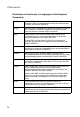
COMPLIANCES Important! Before making connections, make sure you have the correct cord set. Check it (read the label on the cable) against the following: Power Cord Set U.S.A. and Canada The cord set must be UL-approved and CSA certified. The minimum specifications for the flexible cord are: - No. 18 AWG - not longer than 2 meters, or 16 AWG.
COMPLIANCES Veuillez lire à fond l'information de la sécurité suivante avant d'installer le access point: AVERTISSEMENT: L’installation et la dépose de ce groupe doivent être confiés à un personnel qualifié. • Ne branchez pas votre appareil sur une prise secteur (alimentation électrique) lorsqu'il n'y a pas de connexion de mise à la terre (mise à la masse). • Vous devez raccorder ce groupe à une sortie mise à la terre (mise à la masse) afin de respecter les normes internationales de sécurité.
COMPLIANCES Cordon électrique - Il doit être agréé dans le pays d’utilisation Suisse: La prise mâle d’alimentation doit respecter la norme SEV/ ASE 1011. Europe La prise secteur doit être conforme aux normes CEE 7/7 (“SCHUKO”) LE cordon secteur doit porter la mention ou et doit être de type HO3VVF3GO.75 (minimum).
COMPLIANCES Stromkabel. Dies muss von dem Land, in dem es benutzt wird geprüft werden: U.S.A und Kanada Der Cord muß das UL gepruft und war das CSA beglaubigt. Das Minimum spezifikation fur der Cord sind: - Nu. 18 AWG - nicht mehr als 2 meter, oder 16 AWG. - Der typ SV oder SJ - 3-Leiter Der Cord muß haben eine strombelastbarkeit aus wenigstens 10 A Dieser Stromstecker muß hat einer erdschluss mit der typ NEMA 5-15P (15A, 125V) oder NEMA 6-15P (15A, 250V) konfiguration.
COMPLIANCES x
Table of Contents Chapter 1: Introduction Package Checklist Hardware Description Component Description Features and Benefits System Defaults 1-1 1-2 1-2 1-3 1-5 1-6 Chapter 2: Hardware Installation 2-1 Chapter 3: External Antennas 3-1 Installation Procedures Chapter 4: Network Configuration Network Topologies Ad Hoc Wireless LAN (no Access Point) Infrastructure Wireless LAN Infrastructure Wireless LAN for Roaming Wireless PCs Infrastructure Wireless Bridge Infrastructure Wireless Repeater 3-1 4-1 4-2
Contents VLAN WDS Settings AP Management Administration System Log SNMP Configuring SNMP and Trap Message Parameters Configuring SNMPv3 Users Configuring SNMPv3 Trap Filters Configuring SNMPv3 Targets Radio Interface Security Status Information Access Point Status Station Status Event Logs Chapter 7: Command Line Interface Using the Command Line Interface Accessing the CLI Console Connection Telnet Connection Entering Commands Keywords and Arguments Minimum Abbreviation Command Completion Getting Help on Co
Contents country prompt system name username password ip ssh-server enable ip ssh-server port ip telnet-server enable ip http port ip http server ip https port ip https server web-redirect APmgmtIP APmgmtUI show apmagement show system show version show config show hardware System Logging Commands logging on logging host logging console logging level logging facility-type logging clear show logging show event-log System Clock Commands sntp-server ip sntp-server enable sntp-server date-time sntp-server daylig
Contents snmp-server host snmp-server trap snmp-server engine-id snmp-server user snmp-server targets snmp-server filter snmp-server filter-assignments show snmp groups show snmp users show snmp group-assignments show snmp target show snmp filter show snmp filter-assignments show snmp Flash/File Commands bootfile copy delete dir show bootfile RADIUS Client radius-server address radius-server port radius-server key radius-server retransmit radius-server timeout radius-server port-accounting radius-server tim
Contents Filtering Commands filter local-bridge filter ap-manage filter uplink enable filter uplink filter ethernet-type enable filter ethernet-type protocol show filters WDS Bridge Commands bridge role (WDS) bridge-link parent bridge-link child bridge dynamic-entry age-time show bridge aging-time show bridge filter-entry show bridge link Spanning Tree Commands bridge stp enable bridge stp forwarding-delay bridge stp hello-time bridge stp max-age bridge stp priority bridge-link path-cost bridge-link port-pr
Contents beacon-interval dtim-period fragmentation-length rts-threshold super-g description ssid closed-system max-association assoc-timeout-interval auth-timeout-value shutdown show interface wireless show station Rogue AP Detection Commands rogue-ap enable rogue-ap authenticate rogue-ap duration rogue-ap interval rogue-ap scan show rogue-ap Wireless Security Commands auth encryption key transmit-key cipher-suite mic_mode wpa-pre-shared-key pmksa-lifetime pre-authentication Link Integrity Commands link-int
Contents wmm wmm-acknowledge-policy wmmparam 7-131 7-131 7-132 Appendix A: Troubleshooting A-1 Appendix B: Cables and Pinouts B-1 Twisted-Pair Cable Assignments 10/100BASE-TX Pin Assignments Straight-Through Wiring Crossover Wiring Console Port Pin Assignments Wiring Map for Serial Cable B-1 B-1 B-2 B-3 B-3 B-4 Appendix C: Specifications C-1 General Specifications Sensitivity Transmit Power Operating Range C-1 C-4 C-4 C-6 Glossary Index xvii
Contents xviii
Chapter 1: Introduction The 2.4 GHz Wireless Access Point is an IEEE 802.11b/g access point that provides transparent, wireless high-speed data communications between the wired LAN and fixed or mobile devices equipped with an 802.11b, or 802.11g wireless adapter. This solution offers fast, reliable wireless connectivity with considerable cost savings over wired LANs (which include long-term maintenance overhead for cabling). Using 802.11b and 802.
1 Introduction Package Checklist The 2.4 GHz Wireless Access Point package includes: • • • • • • One 2.4 GHz Wireless Access Point One Category 5 network cable One RS-232 console cable One AC power adapter and power cord Four rubber feet User Guide CD Inform your dealer if there are any incorrect, missing or damaged parts. If possible, retain the carton, including the original packing materials. Use them again to repack the product in case there is a need to return it.
1 Hardware Description Rear Panel RJ-45 Management Port Security Slot 5 VDC Power Socket Reset Button Console Port Component Description Antennas The access point includes integrated diversity antennas for wireless communications. A diversity antenna system uses two identical antennas to receive and transmit signals, helping to avoid multipath fading effects. When receiving, the access point checks both antennas and selects the one with the strongest signal.
1 Introduction LED Status PWR On Description Indicates that the system is working normally. Flashing Indicates running a self-test or loading the software program. Flashing (Prolonged) Indicates system errors. Link 11g On Indicates a valid 10/100 Mbps Ethernet cable link. Flashing Indicates that the access point is transmitting or receiving data on a 10/100 Mbps Ethernet LAN. Flashing rate is proportional to network activity. On Indicates that the 802.11b/g radio is enabled.
Features and Benefits 1 Reset Button This button is used to reset the access point or restore the factory default configuration. If you hold down the button for less than 5 seconds, the access point will perform a hardware reset. If you hold down the button for 5 seconds or more, any configuration changes you may have made are removed, and the factory default configuration is restored to the access point. Power Connector The access point does not have a power switch.
1 Introduction System Defaults The following table lists some of the access point’s basic system defaults. To reset the access point defaults, use the CLI command “reset configuration” from the Exec level prompt. Table 1-1.
System Defaults 1 Table 1-1. System Defaults Feature Parameter Default MAC Authentication MAC Disabled 802.
1 Introduction Table 1-1. System Defaults Feature Parameter Default System Logging Syslog Disabled Logging Host Disabled Logging Console Disabled IP Address / Host Name 0.0.0.0 Logging Level Informational Logging Facility Type 16 SNTP Server Status Enabled SNTP Server 1 IP 137.92.140.80 SNTP Server 2 IP 192.43.244.
System Defaults 1 Table 1-1. System Defaults Feature Parameter Default Wireless Interface 802.11b/g (contd.) Antenna ID 0x0000 Antenna Location Indoor Wireless Security 802.
1 Introduction 1-10
Chapter 2: Hardware Installation 1. Select a Site – Choose a proper place for the access point. In general, the best location is at the center of your wireless coverage area, within line of sight of all wireless devices. Try to place the access point in a position that can best cover its Basic Service Set (refer to “Infrastructure Wireless LAN” on page 4-3). For optimum performance, consider these points: • Mount the access point as high as possible above any obstructions in the coverage area.
2 3. Hardware Installation Connect the Power Cord – Connect the power adapter to the access point, and the power cord to an AC power outlet. Otherwise, the access point can derive its operating power directly from the RJ-45 port when connected to a device that provides IEEE 802.3af compliant Power over Ethernet (PoE). Note: If the access point is connected to both a PoE source device and an AC power source, AC power will be disabled. Caution: Use ONLY the power adapter supplied with this access point.
Chapter 3: External Antennas The SMC2552W-G2 provides a variety of external antenna options for extending the radio range and shaping the coverge area. These antennas offer a number of different mounting locations, including indoor or outdoor, wall, ceiling, or radio mast. This chapter shows you how to install an external antenna for your SMC2552W-G2. Note: The use of external antennas with the access point requires professional personnel that are trained in the installation of radio transmitting equipment.
3 External Antennas • Omnidirectional Antennas - Consider these factors when selecting a location for these antennas: • Always mount the antenna in a vertical orientation so that the radio coverage pattern fills the intended horizontal space. • For optimum coverage, mount the antenna at the center of the area with a line-of-sight path to all points within the area.
Installation Procedures 3 To connect pigtail cables to the access point, follow these steps: 1. Disable the access point radio using the web browser interface, CLI, or SNMP. 2. Remove power to the access point. 3. Remove both of the access point’s antennas by unscrewing them at their base. Unscrew antenna to remove 4. For diversity antennas, connect the antenna pigtail cables to the exposed Reverse SMA connectors on both sides of the access point.
3 5. External Antennas Reconnect power to the access point. Note: Before enabling the radio with an external antenna attached, be sure to first configure the access point’s antenna mode.
Chapter 4: Network Configuration Wireless networks support a stand-alone configuration as well as an integrated configuration with 10/100 Mbps Ethernet LANs. The 2.4 GHz Wireless Access Point also provides repeater and bridging services that can be configured independently on 2.4 GHz radio interfaces.
4 Network Configuration Network Topologies Ad Hoc Wireless LAN (no Access Point) An ad hoc wireless LAN consists of a group of computers, each equipped with a wireless adapter, connected via radio signals as an independent wireless LAN. Computers in a specific ad hoc wireless LAN must therefore be configured to the same radio channel. An ad hoc wireless LAN can be used for a branch office or SOHO operation.
Network Topologies 4 Infrastructure Wireless LAN The access point also provides access to a wired LAN for wireless workstations. An integrated wired/wireless LAN is called an Infrastructure configuration. A Basic Service Set (BSS) consists of a group of wireless PC users, and an access point that is directly connected to the wired LAN.
4 Network Configuration Infrastructure Wireless LAN for Roaming Wireless PCs The Basic Service Set (BSS) defines the communications domain for each access point and its associated wireless clients. The BSS ID is a 48-bit binary number based on the access point’s wireless MAC address, and is set automatically and transparently as clients associate with the access point. The BSS ID is used in frames sent between the access point and its clients to identify traffic in the service area.
4 Network Topologies Infrastructure Wireless Bridge The IEEE 802.11 standard defines a WIreless Distribution System (WDS) for bridge connections between BSS areas (access points). The access point uses WDS to forward traffic on links between units. The access point supports WDS bridge links on the 2.4 GHz (802.11b/g) band and can be used with various external antennas to offer flexible deployment options. Up to six WDS bridge links can be specified for each unit in the wireless bridge network.
4 Network Configuration Infrastructure Wireless Repeater The access point can also operate in a bridge “repeater” mode to extend the range of links to wireless clients. The access point uses WDS to forward traffic between the repeater bridge and the root bridge. The access point supports up to six WDS repeater links. In repeater mode, the access point does not support an Ethernet link to a wired LAN. Note that when the access point operates in this mode only half the normal throughput is possible.
Chapter 5: Initial Configuration The 2.4 GHz Wireless Access Point offers a variety of management options, including a web-based interface, a direct connection to the console port, Telnet, Secure Shell (SSH), or using SNMP software. The initial configuration steps can be made through the web browser interface or CLI. The access point requests an IP address via DHCP by default. If no response is received from the DHCP server, then the access point uses the default address 192.168.2.2.
5 Initial Configuration Note: When using HyperTerminal with Microsoft® Windows® 2000, make sure that you have Windows 2000 Service Pack 2 or later installed. Windows 2000 Service Pack 2 fixes the problem of arrow keys not functioning in HyperTerminal’s VT100 emulation. See www.microsoft.com for information on Windows 2000 service packs. 4. Once you have set up the terminal correctly, press the [Enter] key to initiate the console connection. The console login screen will be displayed.
5 Logging In After configuring the access point’s IP parameters, you can access the management interface from anywhere within the attached network. The command line interface can also be accessed using Telnet from any computer attached to the network. Setting the Country Code – Units sold in the United States are configured by default to use only radio channels 1-11 in 802.11b or 802.11g mode as defined by FCC regulations. Units sold in other countries are configured by default without a country code (i.
5 Initial Configuration The home page displays the Main Menu.
Chapter 6: System Configuration Before continuing with advanced configuration, first complete the initial configuration steps described in Chapter 4 to set up an IP address for the access point. The access point can be managed by any computer using a web browser (Internet Explorer 5.0 or above, or Netscape Navigator 6.2 or above). Enter the configured IP address of the access point, or use the default address: http://192.168.2.
6 System Configuration Advanced Configuration The Advanced Configuration pages include the following options. Table 6-2.
Advanced Configuration 6 Table 6-2. Menu Menu Description Page Station Station Shows the wireless clients currently associated with the access point 6-85 Event Logs Shows log messages stored in memory 6-88 System Identification The system name for the access point can be left at its default setting. However, modifying this parameter can help you to more easily distinguish different devices in your network.
6 System Configuration CLI Commands for System Identification – Enter the global configuration mode, and use the system name command to specify a new system name. Then return to the Exec mode, and use the show system command to display the changes to the system identification settings. Enterprise Enterprise Enterprise Enterprise AP#config AP(config)#system name R&D AP(config)#end AP#show system Enterprise AP#config Enter configuration commands, one per line.
6 Advanced Configuration TCP / IP Settings Configuring the access point with an IP address expands your ability to manage the access point. A number of access point features depend on IP addressing to operate. Note: You can use the web browser interface to access IP addressing only if the access point already has an IP address that is reachable through your network. By default, the access point will be automatically configured with IP settings from a Dynamic Host Configuration Protocol (DHCP) server.
6 System Configuration • Subnet Mask: The mask that identifies the host address bits used for routing to specific subnets. • Default Gateway: The default gateway is the IP address of the router for the access point, which is used if the requested destination address is not on the local subnet. If you have management stations, DNS, RADIUS, or other network servers located on another subnet, type the IP address of the default gateway router in the text field provided.
6 Advanced Configuration RADIUS Remote Authentication Dial-in User Service (RADIUS) is an authentication protocol that uses software running on a central server to control access to RADIUS-aware devices on the network. An authentication server contains a database of user credentials for each user that requires access to the network. A primary RADIUS server must be specified for the access point to implement IEEE 802.1X network access control and Wi-Fi Protected Access (WPA) wireless security.
6 6-8 System Configuration
6 Advanced Configuration MAC Address Format – MAC addresses can be specified in one of four formats, using no delimeter, with a single dash delimeter, with multiple dash delimeters, and with multiple colon delimeters. VLAN ID Format – A VLAN ID (a number between 1 and 4094) can be assigned to each client after successful authentication using IEEE 802.1X and a central RADIUS server. The user VLAN IDs must be configured on the RADIUS server for each user authorized to access the network.
6 System Configuration CLI Commands for RADIUS – From the global configuration mode, use the radius-server address command to specify the address of the primary or secondary RADIUS servers. (The following example configures the settings for the primary RADIUS server.) Configure the other parameters for the RADIUS server. Then use the show show radius command from the Exec mode to display the current settings for the primary and secondary RADIUS servers.
Advanced Configuration 6 SSH Settings Telnet is a remote management tool that can be used to configure the access point from anywhere in the network. However, Telnet is not secure from hostile attacks. The Secure Shell (SSH) can act as a secure replacement for Telnet. The SSH protocol uses generated public keys to encrypt all data transfers passing between the access point and SSH-enabled management station clients and ensures that data traveling over the network arrives unaltered.
6 System Configuration CLI Commands for SSH – To enable the SSH server, use the ip ssh-server enable command from the CLI Ethernet interface configuration mode. To set the SSH server UDP port, use the ip ssh-server port command. To view the current settings, use the show system command from the CLI Exec mode (not shown in the following example).
Advanced Configuration 6 MAC Authentication – You can configure a list of the MAC addresses for wireless clients that are authorized to access the network. This provides a basic level of authentication for wireless clients attempting to gain access to the network. A database of authorized MAC addresses can be stored locally on the access point or remotely on a central RADIUS server. (Default: Disabled) • Disabled: No checks are performed on an associating station’s MAC address.
6 System Configuration 802.1X Supplicant – The access point can also operate in a 802.1X supplicant mode. This enables the access point itself to be authenticated with a RADIUS server using a configured MD5 user name and password. This prevents rogue access points from gaining access to the network. Note: Enabling Web Redirect will cause the system to reboot after 5 seconds. Local MAC Authentication – Configures the local MAC authentication database.
Advanced Configuration 6 CLI Commands for Local MAC Authentication – Use the mac-authentication server command from the global configuration mode to enable local MAC authentication. Use the mac-authentication session-timeout command to set the authentication interval, and web-redirect command to enable web-based authentication for service billing.
6 System Configuration CLI Commands for RADIUS MAC Authentication – Use the mac-authentication server command from the global configuration mode to enable remote MAC authentication. Set the timeout value for re-authentication using the macauthentication session-timeout command. Be sure to also configure connection settings for the RADIUS server (not shown in the following example). To display the current settings, use the show authentication command from the Exec mode.
Advanced Configuration 6 Filter Control The access point can employ network traffic frame filtering to control access to network resources and increase security. You can prevent communications between wireless clients and prevent access point management from wireless clients. Also, you can block specific Ethernet traffic from being forwarded by the access point.
6 System Configuration • MAC Address: Specifies a MAC address to filter, in the form xx-xx-xx-xx-xx-xx. • Permission: Adds or deletes a MAC address from the filtering table. Ethernet Type Filter – Controls checks on the Ethernet type of all incoming and outgoing Ethernet packets against the protocol filtering table. (Default: Disabled) • Disabled: Access point does not filter Ethernet protocol types.
Advanced Configuration 6 VLAN The access point can employ VLAN tagging support to control access to network resources and increase security. VLANs separate traffic passing between the access point, associated clients, and the wired network. There can be a VLAN assigned to each associated client, a default VLAN for each VAP (Virtual Access Point) interface, and a management VLAN for the access point.
6 System Configuration When setting up VLAN IDs for each user on the RADIUS server, be sure to use the RADIUS attributes and values as indicated in the following table. Number RADIUS Attribute Value 64 Tunnel-Type VLAN (13) 65 Tunnel-Medium-Type 802 81 Tunnel-Private-Group-ID VLANID (1 to 4094 as hexadecimal or string) VLAN IDs on the RADIUS server can be entered as hexadecimal digits or a string (see “radius-server vlan-format” on page 7-63).
Advanced Configuration 6 WDS Settings Each access point radio interface can be configured to operate in a bridge or repeater mode, which allows it to forward traffic directly to other access point units. To set up bridge links between access point units, you must configure the wireless Distribution System (WDS) forwarding table by specifying the wireless MAC address of all units to which you want to forward traffic.
6 System Configuration • Bridge: Operates as a bridge to other access points. The “Parent” link to the root bridge must be configured. Up to five other ”Child” links are available to other bridges. • Repeater: Operates as a wireless repeater, extending the range for remote wireless clients and connecting them to the root bridge. The “Parent” link to the root bridge must be configured. In this mode, traffic is not forwarded to the Ethernet port from the radio interface.
Advanced Configuration 6 Spanning Tree Protocol – STP uses a distributed algorithm to select a bridging device (STP-compliant switch, bridge or router) that serves as the root of the spanning tree network. It selects a root port on each bridging device (except for the root device) which incurs the lowest path cost when forwarding a packet from that device to the root device.
6 System Configuration designated ports. After determining the lowest cost spanning tree, it enables all root ports and designated ports, and disables all other ports. Network packets are therefore only forwarded between root ports and designated ports, eliminating any possible network loops. Once a stable network topology has been established, all bridges listen for Hello BPDUs (Bridge Protocol Data Units) transmitted from the root bridge.
Advanced Configuration 6 • Link Path Cost – This parameter is used by the STP to determine the best path between devices. Therefore, lower values should be assigned to ports attached to faster media, and higher values assigned to ports with slower media. (Path cost takes precedence over port priority.) • Range: 1-65535 • Default: Ethernet interface: 19; Wireless interface: 40 • Link Port Priority – Defines the priority used for this port in the Spanning Tree Protocol.
6 System Configuration CLI Commands for STP Settings – If the role of a radio interface is set to Repeater, Bridge or Root Bridge, STP can be enabled on the access point to maintain a valid network topology. To globally enable STP, use the bridge stp enable command from the CLI configuration mode. Then configure the other global STP parameters for the bridge.
Advanced Configuration 6 AP Management The Web, Telnet, and SNMP management interfaces are enabled and open to all IP addresses by default. To provide more security for management access to the access point, specific interfaces can be disabled and management restricted to a single IP address or a limited range of IP addresses. Once you specify an IP address or range of addresses, access to management interfaces is restricted to the specified addresses.
6 System Configuration CLI Commands for AP Management features. Enterprise AP(config)#apmgmtip multiple 192.168.1.50 255.255.255.0 Enterprise AP(config)#apmgmtui SNMP enable 7-21 7-22 Administration Changing the Password Management access to the web and CLI interface on the access point is controlled through a single user name and password. You can also gain additional access security by using control filters (see “Filter Control” on page 6-17).
Advanced Configuration 6 Upgrading Firmware You can upgrade new access point software from a local file on the management workstation, or from an FTP or TFTP server. New software may be provided periodically from your distributor. After upgrading new software, you must reboot the access point to implement the new code. Until a reboot occurs, the access point will continue to run the software it was using before the upgrade started.
6 System Configuration Before upgrading new software, verify that the access point is connected to the network and has been configured with a compatible IP address and subnet mask. If you need to download from an FTP or TFTP server, take the following additional steps: • Obtain the IP address of the FTP or TFTP server where the access point software is stored. • If upgrading from an FTP server, be sure that you have an account configured on the server with a user name and password.
Advanced Configuration 6 CLI Commands for Downloading Software from a TFTP Server – Use the copy tftp file command from the Exec mode and then specify the file type, name, and IP address of the TFTP server. When the download is complete, the dir command can be used to check that the new file is present in the access point file system. To run the new software, use the reset board command to reboot the access point. Enterprise AP#copy tftp file 1. Application image 2. Config file 3.
6 System Configuration System Log The access point can be configured to send event and error messages to a System Log Server. The system clock can also be synchronized with a time server, so that all the messages sent to the Syslog server are stamped with the correct time and date. Enabling System Logging The access point supports a logging process that can control error messages saved to memory or sent to a Syslog server.
Advanced Configuration 6 Logging Level – Sets the minimum severity level for event logging. (Default: Informational) The system allows you to limit the messages that are logged by specifying a minimum severity level. The following table lists the error message levels from the most severe (Emergency) to least severe (Debug). The message levels that are logged include the specified minimum level up to the Emergency level.
6 System Configuration CLI Commands for System Logging – To enable logging on the access point, use the logging on command from the global configuration mode. The logging level command sets the minimum level of message to log. Use the logging console command to enable logging to the console. Use the logging host command to specify up to four Syslog servers. The CLI also allows the logging facility-type command to set the facility-type number to use on the Syslog server.
Advanced Configuration 6 Note: The access point also allows you to disable SNTP and set the system clock manually. Set Time Zone – SNTP uses Coordinated Universal Time (or UTC, formerly Greenwich Mean Time, or GMT) based on the time at the Earth’s prime meridian, zero degrees longitude. To display a time corresponding to your local time, you must indicate the number of hours your time zone is located before (east) or after (west) UTC.
6 System Configuration CLI Commands for the System Clock – The following example shows how to manually set the system time when SNTP server support is disabled on the access point.
SNMP 6 Configuring SNMP and Trap Message Parameters The access point SNMP agent must be enabled to function (for versions 1, 2c, and 3 clients). Management access using SNMP v1 and v2c also requires community strings to be configured for authentication. Trap notifications can be enabled and sent to up to four management stations. SNMP – Enables or disables SNMP management access and also enables the access point to send SNMP traps (notifications).
6 System Configuration Community Name (Read/Write) – Defines the SNMP community access string that has read/write access. Authorized management stations are able to both retrieve and modify MIB objects. (Maximum length: 23 characters, case sensitive; Default: private) Trap Destination (1 to 4) – Enables recipients (up to four) of SNMP notifications. • Trap Destination IP Address – Specifies the recipient of SNMP notifications. Enter the IP address or the host name.
SNMP 6 Trap Configuration – Allows selection of specific SNMP notifications to send. The following items are available: • sysSystemUp - The access point is up and running. • sysSystemDown - The access point is about to shutdown and reboot. • sysRadiusServerChanged - The access point has changed from the primary RADIUS server to the secondary, or from the secondary to the primary. • sysConfigFileVersionChanged - The access point’s configuration file has been changed.
6 System Configuration • dot11StationAuthenticateFail - A client station has tried and failed to authenticate to the network. • Enable All Traps - Click the button to enable all the available traps. • Disable All Traps - Click the button to disable all the available traps. CLI Commands for SNMP and Trap Configuration – Use the snmp-server enable server command from the global configuration mode to enable the SNMP agent.
SNMP 6 To view the current SNMP settings, use the show snmp command. Enterprise AP#show snmp 7-54 SNMP Information ============================================== Service State : Enable Community (ro) : ***** Community (rw) : ***** Location : WC-19 Contact : Paul EngineId :80:00:07:e5:80:00:00:2e:62:00:00:00:18 EngineBoots:1 Trap Destinations: 1: 192.168.1.9, 2: 0.0.0.0, 3: 0.0.0.0, 4: 0.0.0.
6 System Configuration Configuring SNMPv3 Users The access point allows up to 10 SNMP v3 users to be configured. Each user must be defined by a unique name, assigned to one of three pre-defined security groups, and configured with specific authentication and encryption settings. User – The SNMPv3 user name. (32 characters maximum) Group – The SNMPv3 group name. (Options: RO, RWAuth, or RWPriv; Default: RO) • RO – Read-only access. • RWAuth – Read/write access with user authentication.
SNMP 6 CLI Commands for Configuring SNMPv3 Users – Use the snmp-server engine-id command to define the SNMP v3 engine before assigning users to groups. Use the snmp-server user command to assign users to one of the three groups and set the appropriate authentication and encryption types to be used. To view the current SNMP v3 engine ID, use the show snmp command. To view SNMP users and group settings, use the show snmp users or show snmp group-assignments commands.
6 System Configuration Configuring SNMPv3 Trap Filters SNMP v3 users can be configured to receive notification messages from the access point. An SNMP Target ID is created that specifies the SNMP v3 user, IP address, and UDP port. A user-defined notification filter can be created so that specific notifications can be prevented from being sent to particular targets. The access point allows up to 10 notification filters to be created. Each filter can be defined by up to 20 MIB subtree ID entries.
SNMP 6 Note: Only the New Filter page allows the Filter ID to be configured. Filter ID – A user-defined name that identifies the filter. (Maximum length: 32 characters) Subtree OID – Specifies MIB subtree to be filtered. The MIB subtree must be defined in the form “.1.3.6.1” and always start with a “.”. Filter Type – Indicates if the filter is to “include” or “exclude” the MIB subtree objects from the filter.
6 System Configuration Configuring SNMPv3 Targets An SNMP v3 notification Target ID is specified by the SNMP v3 user, IP address, and UDP port. A user-defined filter can also be assigned to specific targets to limit the notifications received to specific MIB objects. (Note that the filter must first be configured. see “Configuring SNMPv3 Trap Filters” on page 6-44) To configure a new notification receiver target, click the New button. A new page opens to configure the settings (see below).
SNMP 6 Target ID – A user-defined name that identifies a receiver of notifications. The access point supports up to 10 target IDs. (Maximum length: 32 characters) IP Address – Specifies the IP address of the receiving management station. UDP Port – The UDP port that is used on the receiving management station for notification messages. SNMP User – The defined SNMP v3 user that is to receive notification messages.
6 System Configuration Enterprise AP(config)#snmp-server targets mytraps 192.168.1.33 chris Enterprise AP(config)#snmp-server filter-assignment mytraps trapfilter Enterprise AP(config)#exit Enterprise AP#show snmp target Host ID : mytraps User : chris IP Address : 192.168.1.33 UDP Port : 162 ============================= Enterprise AP#show snmp filter-assignments HostID mytraps 7-48 7-50 7-52 7-53 FilterID trapfilter Enterprise AP# Radio Interface The IEEE 802.
Radio Interface 6 Radio Channel – The radio channel that the access point uses to communicate with wireless clients. When multiple access points are deployed in the same area, set the channel on neighboring access points at least five channels apart to avoid interference with each other. For example, in the United States you can deploy up to three access points in the same area (e.g., channels 1, 6, 11).
6 System Configuration Maximum Station Data Rate – The maximum data rate at which the access point transmits unicast packets on the wireless interface. The maximum transmission distance is affected by the data rate. The lower the data rate, the longer the transmission distance. (Default: 54 Mbps) Maximum Associated Clients – Sets the maximum number of clients that can be associated with a VAP interface at the same time.
Radio Interface 6 Super G – The Atheros proprietary Super G performance enhancements are supported by the access point. These enhancements include bursting, compression, fast frames and dynamic turbo. Maximum throughput ranges between 40 to 60 Mbps for connections to Atheros-compatible clients. (Default: Disabled) Radio Mode – Selects the operating mode for the 802.11g wireless interface. (Default: 802.11b+g) • 802.11b+g: Both 802.11b and 802.
6 System Configuration Fragmentation Length – Configures the minimum packet size that can be fragmented when passing through the access point. Fragmentation of the PDUs (Package Data Unit) can increase the reliability of transmissions because it increases the probability of a successful transmission due to smaller frame size. If there is significant interference present, or collisions due to high network utilization, try setting the fragment size to send smaller fragments.
Radio Interface 6 CLI Commands for Radio Settings – From the global configuration mode, enter the interface wireless g command to access the 802.11g radio interface. From the 802.11g interface mode, you can access radio settings that apply to all VAP interfaces. Use the turbo command to enable this feature before setting the radio channel with the channel command. Set any other radio setting as required before enabling the VAP interface (with the no shutdown command). To view the current 802.
6 System Configuration Configuring VAP Radio Settings To configure VAP radio settings, select the Radio Settings page. Default VLAN ID – The VLAN ID assigned to wireless clients associated to the VAP interface that are not assigned to a specific VLAN by RADIUS server configuration. (Default: 1) Closed System – When enabled, the VAP interface does not include its SSID in beacon messages. Nor does it respond to probe requests from clients that do not include a fixed SSID.
Radio Interface 6 WPA2 PMKSA Life Time – WPA2 provides fast roaming for authenticated clients by retaining keys and other security settings in a cache for each VAP. In this way, when clients roam back into a VAP they had previously been using, re-authentication is not required. When a WPA2 client is first authenticated, it receives a Pairwise Master Key (PMK) that is used to generate the other keys used for unicast data encryption.
6 System Configuration Rogue AP – A “rogue AP” is either an access point that is not authorized to participate in the wireless network, or an access point that does not have the correct security configuration. Rogue APs can allow unauthorized access to the network, or fool client stations into mistakenly associating with them and thereby blocking access to network resources. The access point can be configured to periodically scan all radio channels and find other access points within range.
Radio Interface 6 rogue-ap scan command. To view the database of detected access points, use the show rogue-ap command from the Exec level. Enterprise AP(config)#interface wireless g 7-88 Enter Wireless configuration commands, one per line. Enterprise AP(if-wireless g)#rogue-ap enable 7-110 configure either syslog or trap or both to receive the rogue APs detected.
6 System Configuration Table 6-1. WMM Access Categories Access Category WMM Designation Description 802.1D Tags AC_VO (AC3) Voice Highest priority, minimum delay. Time-sensitive data such as VoIP (Voice over IP) calls. 7, 6 AC_VI (AC2) Video High priority, minimum delay. Time-sensitive data 5, 4 such as streaming video. AC_BE (AC0) Best Effort Normal priority, medium delay and throughput. 0, 3 Data only affected by long delays. Data from applications or devices that lack QoS capabilities.
Radio Interface 6 Tim CWMin riority CWMax AIFS Random Backoff Minimum Wait Time Random Wait Time CWMin riority C AIFS Random Backoff Minimum Wait Time Random Wait Time Figure 6-1. WMM Backoff Wait Times For high-priority traffic, the AIFSN and CW values are smaller. The smaller values equate to less backoff and wait time, and therefore more transmit opportunities. To configure WMM, select the Radio Settings page, and scroll down to the WMM configuration settings.
6 System Configuration WMM – Sets the WMM operational mode on the access point. When enabled, the parameters for each AC queue will be employed on the access point and QoS capabilities are advertised to WMM-enabled clients. (Default: Support) • Disable: WMM is disabled. • Support: WMM will be used for any associated device that supports this feature. Devices that do not support this feature may still associate with the access point.
Radio Interface 6 CLI Commands for WMM – Enter interface wireless mode and type wmm required for clients that want to associate with the access point. The wmm-acknowledge-policy command is used to enable or disable a policy for each access category. The wmmparms command defines detailed WMM parameters. Enterprise AP(if-wireless g)#wmm required Enterprise AP(if-wireless g)#wmm-acknowledge-policy 0 noack Enterprise AP(if-wireless g)#wmmparams ap 0 4 6 3 1 1 7-131 7-131 7-132 To view the current 802.
6 System Configuration ----------------Quality of Service--------------------------WMM Mode : SUPPORTED WMM Acknowledge Policy AC0(Best Effort) : Ack AC1(Background) : Acknowledge AC2(Video) : Acknowledge AC3(Voice) : Acknowledge WMM BSS Parameters AC0(Best Effort) : logCwMin: 4 logCwMax: 10 AIFSN: Admission Control: No TXOP Limit: 0.000 ms AC1(Background) : logCwMin: 4 logCwMax: 10 AIFSN: Admission Control: No TXOP Limit: 0.
Radio Interface 6 • Wi-Fi Protected Access (WPA or WPA2)page 6-73 Both WEP and WPA security settings are configurable separately for each virtual access point (VAP) interface. MAC address filtering, and RADIUS server settings are global and apply to all VAP interfaces. The security mechanisms that may be employed depend on the level of security required, the network and management resources available, and the software support provided on wireless clients.
6 System Configuration Table 6-2. Wireless Security Considerations Security Mechanism Client Support Implementation Considerations WPA2 with 802.1X Requires WPA-enabled system • Provides the strongest security in WPA2-only and network card driver (native mode support provided in Windows • Provides robust security in mixed mode for WPA XP) and WPA2 clients • Offers fast roaming for time-sensitive client applications • Requires configured RADIUS server • 802.
Radio Interface 6 Table 6-3. Security Combinations Client Security Combination 802.1x WPA only Configuration Summarya Interface Detail Settings: Authentication: WPA Encryption: Enable WPA Clients: Required Cipher Suite: TKIP 802.1x: Required Set 802.1x key refresh and reauthentication rates MAC RADIUS Authenticationb Server Local only Yes WPA Pre-Shared Key Interface Detail Settings: only Authentication: WPA-PSK Encryption: Enable WPA Clients: Required Cipher Suite: TKIP 802.
6 System Configuration Table 6-3. Security Combinations Client Security Combination Configuration Summarya MAC RADIUS Authenticationb Server WPA2 Pre-Shared Key only Interface Detail Settings: Authentication: WPA2-PSK Encryption: Enable WPA Clients: Required Cipher Suite: AES-CCMP 802.1x: Disable WPA Pre-shared Key Type: Hexadicmal or Alphanumeric Enter a WPA Pre-shared key Local or Disabled No 802.
Radio Interface 6 Before enabling the radio service for any VAP, first configure the WEP, WPA, and 802.1X security settings described in the following sections. After you have finished configuring the security settings, return to the main Security page shown below, start the required VAP interfaces by clicking the Enable checkbox, and then click Apply.
6 System Configuration Enable – Enables radio communications on the VAP interface. (Default: Disabled) Note: You must first enable VAP interface 0 before you can enable other VAP interfaces. SSID – The name of the basic service set provided by a VAP interface. Clients that want to connect to the network through the access point must set their SSID to the same as that of an access point VAP interface.
Radio Interface 6 • Alphanumeric: Enter keys as 5 alphanumeric characters for 64 bit keys, 13 alphanumeric characters for 128 bit keys, or 16 alphanumeric characters for 152 bit keys. Key Number – Selects the key number to use for encryption for each VAP interface. If the clients have all four keys configured to the same values, you can change the encryption key to any of the eight settings without having to update the client keys.
6 System Configuration Note: To use 802.1X on wireless clients requires a network card driver and 802.1X client software that supports the EAP authentication type that you want to use. Windows 2000 SP3 or later and Windows XP provide 802.1X client support. Windows XP also provides native WPA support. Other systems require additional client software to support 802.1X and WPA. Encryption – Enable or disable the access point to use data encryption (WEP, TKIP, or AES).
Radio Interface 6 Enterprise AP(config)#interface wireless g 7-88 Enter Wireless configuration commands, one per line. Enterprise AP(if-wireless g)#key 1 128 ascii abcdeabcdeabc 7-117 Enterprise AP(if-wireless g)#vap 0 7-95 Enterprise AP(if-wireless g: VAP[0])#no 802.
6 System Configuration ----------------Security-----------------------------------------------Closed System : Disabled Multicast cipher : WEP Unicast cipher : TKIP and AES WPA clients : DISABLED WPA Key Mgmt Mode : PRE SHARED KEY WPA PSK Key Type : PASSPHRASE WPA PSK Key : EMPTY PMKSA Lifetime : 720 minutes Encryption : DISABLED Default Transmit Key : 1 Common Static Keys : Key 1: EMPTY Key 2: EMPTY Key 3: EMPTY Key 4: EMPTY Pre-Authentication : DISABLED Authentication Type : OPEN ----------------802.
Radio Interface 6 CLI Commands for WEP over 802.1X Security – Use the vap command to access each VAP interface to configure the security settings. First set 802.1X to required using the 802.1x command and set the 802.1X key refresh rates. Then, use the authentication command to select open system authentication and the encryption command to enable data encryption. To view the current security settings, use the show interface wireless g 0 command (not shown in example).
6 System Configuration WPA Pre-Shared Key Mode (WPA-PSK, WPA2-PSK): For enterprise deployment, WPA requires a RADIUS authentication server to be configured on the wired network. However, for small office networks that may not have the resources to configure and maintain a RADIUS server, WPA provides a simple operating mode that uses just a pre-shared password for network access.
Radio Interface 6 the cipher used for broadcast frames is always TKIP. WEP encryption is not allowed. • Key Caching: WPA2 provides fast roaming for authenticated clients by retaining keys and other security information in a cache, so that if a client roams away from an access point and then returns, re-authentication is not required. When a WPA2 client is first authenticated, it receives a Pairwise Master Key (PMK) that is used to generate other keys for unicast data encryption.
6 System Configuration To configure WPA, click Security under Radio A or Radio G. Select one of the VAP interfaces by clicking More. Select one of the WPA options in the Authentication Setup table, and then configure the parameters displayed beneath the table. The WPA configuration parameters are described below: Encryption – You must enable data encryption in order to enable all types of encryption (WEP, TKIP, or AES) in the access point. Pre-Authentication – When using WPA2 over 802.
Radio Interface 6 • WPA: Clients using WPA over 802.1X are accepted for authentication. • WPA-PSK: Clients using WPA with a Pre-shared Key are accepted for authentication. • WPA2: Clients using WPA2 over 802.1X are accepted for authentication. • WPA2-PSK: Clients using WPA2 with a Pre-shared Key are accepted for authentication. • WPA-WPA2-mixed: Clients using WPA or WPA2 over 802.1X are accepted for authentication.
6 System Configuration CLI Commands for WPA Using Pre-shared Key Security – Be sure to first disable 802.1X port authentication using the 802.1X command from the configuration mode. Then, from the 802.11g interface configuration mode, use the vap command to access each VAP interface to configure other security settings. From the VAP interface configuration mode, use the authentication command to set the access point to “Open System.” Use the encryption command to enable data encryption.
Radio Interface 6 CLI Commands for WPA Over 802.1X Security – First set 802.1X to required using the 802.1X command and set the 802.1X key refresh rates. Then 802.11g interface configuration mode, use the vap command to access each VAP interface to configure other security settings. From the VAP interface configuration mode, use the authentication command to select open system authentication and the encryption command to enable data encryption.
6 System Configuration Open the Security page, and click More for one of the VAP interfaces. You can enable 802.1X as optionally supported or as required to enhance the security of the wireless network. (Default: Disable) • Disable: The access point does not support 802.1X authentication for any wireless client. After successful wireless association with the access point, each client is allowed to access the network. • Supported: The access point supports 802.
Radio Interface 6 • 802.1X Reauthentication Refresh Rate: The time period after which a connected client must be re-authenticated. During the re-authentication process of verifying the client’s credentials on the RADIUS server, the client remains connected the network. Only if re-authentication fails is network access blocked. (Range: 0-65535 seconds; Default: 0 means disabled) CLI Commands for 802.1X Authentication – Use the 802.1X supported command from the VAP interface mode to enable 802.
6 System Configuration Status Information The Status page includes information on the following items: Menu Description Page AP Status Displays configuration settings for the basic system and the wireless interface 6-82 Station Status Shows the wireless clients currently associated with the access point 6-85 Event Logs Shows log messages stored in memory 6-88 Access Point Status The AP Status window displays basic system configuration settings, as well as the settings for the wireless interfac
Status Information 6 AP System Configuration – The AP System Configuration table displays the basic system configuration settings: • • • • • • System Up Time: Length of time the management agent has been up. MAC Address: The physical layer address for this device. System Name: Name assigned to this system. System Contact: Administrator responsible for the system. IP Address: IP address of the management interface for this device.
6 System Configuration CLI Commands for Displaying System Settings – To view the current access point system settings, use the show system command from the Exec mode. To view the current radio interface settings, use the show interface wireless g 0 command (see page 7-108).
Status Information 6 Station Status The Station Status window shows the wireless clients currently associated with the access point. The Station Configuration page displays basic connection information for all associated stations as described below. Note that this page is automatically refreshed every five seconds. • Station Address: The MAC address of the wireless client. • Authenticated: Shows if the station has been authenticated. The two basic methods of authentication supported for 802.
6 • • • • System Configuration shared-key approach uses Wired Equivalent Privacy (WEP) to verify client identity by distributing a shared key to stations before attempting authentication. Associated: Shows if the station has been successfully associated with the access point. Once authentication is completed, stations can associate with the current access point, or reassociate with a new access point.
Status Information 6 CLI Commands for Displaying Station Status – To view status of clients currently associated with the access point, use the show station command from the Exec mode. Enterprise AP#show station 7-109 Station Table Information =========================================================== if-wireless G VAP [0] : 802.11g Channel : Auto No 802.11g Channel Stations. if-wireless G VAP [1] 802.11g Channel : Auto : No 802.11g Channel Stations. .... No 802.11g Channel Stations.
6 System Configuration Event Logs The Event Logs window shows the log messages generated by the access point and stored in memory. The Event Logs table displays the following information: • Log Time: The time the log message was generated. • Event Level: The logging level associated with this message. For a description of the various levels, see “logging level” on page 6-32. • Event Message: The content of the log message.
Status Information 6 CLI Commands for Displaying Event Logs – To view the access point log entries, use the show event-log command from the Exec mode. To clear all log entries from the access point, use the logging clear command from the Global Configuration mode.
6 System Configuration 6-90
Chapter 7: Command Line Interface Using the Command Line Interface Accessing the CLI When accessing the management interface for the over a direct connection to the console port, or via a Telnet connection, the access point can be managed by entering command keywords and parameters at the prompt. Using the access point’s command-line interface (CLI) is very similar to entering commands on a UNIX system. Console Connection To access the access point through the console port, perform these steps: 1.
7 Command Line Interface If your corporate network is connected to another network outside your office or to the Internet, you need to apply for a registered IP address. However, if you are attached to an isolated network, then you can use any IP address that matches the network segment to which you are attached. After you configure the access point with an IP address, you can open a Telnet session by performing these steps. 1.
Entering Commands 7 Command Completion If you terminate input with a Tab key, the CLI will print the remaining characters of a partial keyword up to the point of ambiguity. In the “configure” example, typing con followed by a tab will result in printing the command up to “configure.” Getting Help on Commands You can display a brief description of the help system by entering the help command. You can also display command syntax by following a command with the “?” character to list keywords or parameters.
7 Command Line Interface Partial Keyword Lookup If you terminate a partial keyword with a question mark, alternatives that match the initial letters are provided. (Remember not to leave a space between the command and question mark.) For example “s?” shows all the keywords starting with “s.
Entering Commands 7 Exec Commands When you open a new console session on an access point, the system enters Exec command mode. Only a limited number of the commands are available in this mode. You can access all other commands only from the configuration mode. To access Exec mode, open a new console session with the user name “admin.” The command prompt displays as “Enterprise AP#” for Exec mode.
7 Command Line Interface Command Line Processing Commands are not case sensitive. You can abbreviate commands and parameters as long as they contain enough letters to differentiate them from any other currently available commands or parameters. You can use the Tab key to complete partial commands, or enter a partial command followed by the “?” character to display a list of possible matches. You can also use the following editing keystrokes for command-line processing: Table 7-1.
General Commands 7 Table 7-2. Command Groups Command Group Description Page SNMP Configures community access strings and trap managers 7-41 Flash/File Manages code image or access point configuration files 7-56 RADIUS Configures the RADIUS client used with 802.1X authentication 7-59 802.1X Authentication Configures 802.
7 Command Line Interface configure This command activates Global Configuration mode. You must enter this mode to modify most of the settings on the access point. You must also enter Global Configuration mode prior to enabling the context modes for Interface Configuration. See “Using the Command Line Interface” on page 1. Default Setting None Command Mode Exec Example Enterprise AP#configure Enterprise AP(config)# Related Commands end (7-9) end This command returns to the previous configuration mode.
General Commands 7 Example This example shows how to return to the Exec mode from the Interface Configuration mode, and then quit the CLI session: Enterprise AP(if-ethernet)#exit Enterprise AP#exit CLI session with the Access Point is now closed Username: ping This command sends ICMP echo request packets to another node on the network. Syntax ping • host_name - Alias of the host. • ip_address - IP address of the host.
7 Command Line Interface reset This command restarts the system or restores the factory default settings. Syntax reset • board - Reboots the system. • configuration - Resets the configuration settings to the factory defaults, and then reboots the system. Default Setting None Command Mode Exec Command Usage When the system is restarted, it will always run the Power-On Self-Test.
System Management Commands 7 show line This command displays the console port’s configuration settings. Command Mode Exec Example The console port settings are fixed at the values shown below.
7 Command Line Interface Table 7-4.
System Management Commands 7 Table 7-5.
7 Command Line Interface Command Usage • If you purchased an access point outside of the United States, the country code must be set before radio functions are enabled. • The available Country Code settings can be displayed by using the country ? command. Example Enterprise AP#country tw Enterprise AP# prompt This command customizes the CLI prompt. Use the no form to restore the default prompt. Syntax prompt no prompt string - Any alphanumeric string to use for the CLI prompt.
System Management Commands 7 Command Mode Global Configuration Example Enterprise AP(config)#system name AP Enterprise AP(config)# username This command configures the user name for management access. Syntax username name - The name of the user. (Length: 3-16 characters, case sensitive) Default Setting admin Command Mode Global Configuration Example Enterprise AP(config)#username bob Enterprise AP(config)# password After initially logging onto the system, you should set the password.
7 Command Line Interface ip ssh-server enable This command enables the Secure Shell server. Use the no form to disable the server. Syntax ip ssh-server enable no ip ssh-server Default Setting Interface enabled Command Mode Interface Configuration (Ethernet) Command Usage • The access point supports Secure Shell version 2.0 only. • After boot up, the SSH server needs about two minutes to generate host encryption keys. The SSH server is disabled while the keys are being generated.
System Management Commands 7 ip telnet-server enable This command enables the Telnet server. Use the no form to disable the server. Syntax ip telnet-server enable no ip telnet-server Default Setting Interface enabled Command Mode Interface Configuration (Ethernet) Example Enterprise AP(if-ethernet)#ip telnet-server enable Enterprise AP(if-ethernet)# ip http port This command specifies the TCP port number used by the web browser interface. Use the no form to use the default port.
7 Command Line Interface ip http server This command allows this device to be monitored or configured from a browser. Use the no form to disable this function. Syntax ip http server no ip http server Default Setting Enabled Command Mode Global Configuration Example Enterprise AP(config)#ip http server Enterprise AP(config)# Related Commands ip http port (7-18) ip https port Use this command to specify the UDP port number used for HTTPS/SSL connection to the access point’s Web interface.
System Management Commands 7 Example Enterprise AP(config)#ip https port 1234 Enterprise AP(config)# ip https server Use this command to enable the secure hypertext transfer protocol (HTTPS) over the Secure Socket Layer (SSL), providing secure access (i.e., an encrypted connection) to the access point’s Web interface. Use the no form to disable this function.
7 Command Line Interface web-redirect Use this command to enable web-based authentication of clients. Use the no form to disable this function. Syntax [no] web-redirect Default Setting Disabled Command Mode Global Configuration Command Usage • The web redirect feature is used to support billing for a public access wireless network. After successful association to an access point, a client is “redirected” to an access point login web page as soon as Internet access is attempted.
System Management Commands 7 APmgmtIP This command specifies the client IP addresses that are allowed management access to the access point through various protocols. Caution: Secure Web (HTTPS) connections are not affected by the UI Management or IP Management settings. Syntax APmgmtIP • multiple - Adds IP addresses within a specifiable range to the SNMP, web and Telnet groups. • single - Adds an IP address to the SNMP, web and Telnet groups.
7 Command Line Interface APmgmtUI This command enables and disables management access to the access point through SNMP, Telnet and web interfaces. Caution: Secure Web (HTTPS) connections are not affected by the UI Management or IP Management settings. Syntax APmgmtUI <[SNMP | Telnet | Web] enable | disable> • SNMP - Specifies SNMP management access. • Telnet - Specifies Telnet management access. • Web - Specifies web based management access.
System Management Commands 7 show system This command displays basic system configuration settings.
7 Command Line Interface show version This command displays the software version for the system. Command Mode Exec Example Enterprise AP#show version Version Information ========================================= Software Version : v5.0.0.0 Date : Feb 8 2006, 17:48:27 BootRom Version : v1.1.1 Hardware version : R0A ========================================= Enterprise AP# show config This command displays detailed configuration information for the system.
System Management Commands 7 Hardware Version Information =========================================== Hardware version R01A =========================================== Ethernet Interface Information ======================================== IP Address : 192.168.0.151 Subnet Mask : 255.255.255.0 Default Gateway : 192.168.0.1 Primary DNS : 210.200.211.225 Secondary DNS : 210.200.211.
7 Command Line Interface Logging Information ===================================================== Syslog State : Disabled Logging Console State : Disabled Logging Level : Informational Logging Facility Type : 16 Servers 1: 0.0.0.0 , UDP Port: 514, State: Disabled 2: 0.0.0.0 , UDP Port: 514, State: Disabled 3: 0.0.0.0 , UDP Port: 514, State: Disabled 4: 0.0.0.
System Management Commands dot11InterfaceAGFail dot11StationAssociation dot11StationReAssociation dot1xAuthFail dot1xAuthSuccess dot1xMacAddrAuthSuccess iappStationRoamedFrom localMacAddrAuthFail pppLogonFail configFileVersionChanged systemDown Enabled Enabled Enabled Enabled Enabled Enabled Enabled Enabled Enabled Enabled Enabled dot11InterfaceBFail dot11StationAuthentication dot11StationRequestFail dot1xAuthNotInitiated dot1xMacAddrAuthFail iappContextDataSent iappStationRoamedTo localMacAddrAuthSuccess
7 Command Line Interface SSH Server : ENABLED SSH Server Port : 22 Telnet Server : ENABLED WEB Redirect : DISABLED DHCP Relay : DISABLED ============================================================== Version Information ========================================= Version: v4.3.2.2 Date : Dec 20 2005, 18:38:12 ========================================= Enterprise AP# show hardware This command displays the hardware version of the system.
System Logging Commands 7 logging on This command controls logging of error messages; i.e., sending debug or error messages to memory. The no form disables the logging process. Syntax [no] logging on Default Setting Disabled Command Mode Global Configuration Command Usage The logging process controls error messages saved to memory. You can use the logging level command to control the type of error messages that are stored in memory.
7 Command Line Interface Example Enterprise AP(config)#logging host 1 10.1.0.3 Enterprise AP(config)# logging console This command initiates logging of error messages to the console. Use the no form to disable logging to the console. Syntax logging console no logging console Default Setting Disabled Command Mode Global Configuration Example Enterprise AP(config)#logging console Enterprise AP(config)# logging level This command sets the minimum severity level for event logging.
System Logging Commands 7 Command Usage Messages sent include the selected level down to Emergency level. Level Argument Description Emergency System unusable Alert Immediate action needed Critical Critical conditions (e.g., memory allocation, or free memory error - resource exhausted) Error Error conditions (e.g., invalid input, default used) Warning Warning conditions (e.g.
7 Command Line Interface Command Usage The command specifies the facility type tag sent in syslog messages. (See RFC 3164.) This type has no effect on the kind of messages reported by the access point. However, it may be used by the syslog server to sort messages or to store messages in the corresponding database. Example Enterprise AP(config)#logging facility 19 Enterprise AP(config)# logging clear This command clears all log messages stored in the access point’s memory.
System Clock Commands 7 show event-log This command displays log messages stored in the access point’s memory. Syntax show event-log Command Mode Exec Example Enterprise AP#show event-log Mar 09 11:57:55 Information: Mar 09 11:57:55 Information: Mar 09 11:57:34 Information: Mar 09 11:57:18 Information: Mar 09 11:55:52 Information: Mar 09 11:55:52 Information: Mar 09 11:55:52 Information: Mar 09 11:55:40 Information: Press next. previous.
7 Command Line Interface sntp-server ip This command sets the IP address of the servers to which SNTP time requests are issued. Use the this command with no arguments to clear all time servers from the current list. Syntax sntp-server ip <1 | 2> • 1 - First time server. • 2 - Second time server. • ip - IP address of an time server (NTP or SNTP). Default Setting 137.92.140.80 192.43.244.
System Clock Commands 7 Command Mode Global Configuration Command Usage The time acquired from time servers is used to record accurate dates and times for log events. Without SNTP, the access point only records the time starting from the factory default set at the last bootup (i.e., 00:14:00, January 1, 1970). Example Enterprise AP(config)#sntp-server enable Enterprise AP(config)# Related Commands sntp-server ip (7-35) show sntp (7-38) sntp-server date-time This command sets the system clock.
7 Command Line Interface sntp-server daylight-saving This command sets the start and end dates for daylight savings time. Use the no form to disable daylight savings time. Syntax sntp-server daylight-saving no sntp-server daylight-saving Default Setting Disabled Command Mode Global Configuration Command Usage The command sets the system clock back one hour during the specified period. Example This sets daylight savings time to be used from July 1st to September 1st.
System Clock Commands 7 Command Usage This command sets the local time zone relative to the Coordinated Universal Time (UTC, formerly Greenwich Mean Time or GMT), based on the earth’s prime meridian, zero degrees longitude. To display a time corresponding to your local time, you must indicate the number of hours and minutes your time zone is east (before) or west (after) of UTC.
7 Command Line Interface DHCP Relay Commands Dynamic Host Configuration Protocol (DHCP) can dynamically allocate an IP address and other configuration information to network clients that broadcast a request. To receive the broadcast request, the DHCP server would normally have to be on the same subnet as the client. However, when the access point’s DHCP relay agent is enabled, received client requests can be forwarded directly by the access point to a known DHCP server on another subnet.
DHCP Relay Commands 7 dhcp-relay This command configures the primary and secondary DHCP server addresses. Syntax dhcp-relay • primary - The primary DHCP server. • secondary - The secondary DHCP server. • ip_address - IP address of the server. Default Setting Primary and secondary: 0.0.0.0 Command Mode Global Configuration Example Enterprise AP(config)#dhcp-relay primary 192.168.1.
7 Command Line Interface SNMP Commands Controls access to this access point from management stations using the Simple Network Management Protocol (SNMP), as well as the hosts that will receive trap messages. Table 7-9.
SNMP Commands 7 snmp-server community This command defines the community access string for the Simple Network Management Protocol. Use the no form to remove the specified community string. Syntax snmp-server community string [ro | rw] no snmp-server community string • string - Community string that acts like a password and permits access to the SNMP protocol. (Maximum length: 23 characters, case sensitive) • ro - Specifies read-only access.
7 Command Line Interface Command Mode Global Configuration Example Enterprise AP(config)#snmp-server contact Paul Enterprise AP(config)# Related Commands snmp-server location (7-43) snmp-server location This command sets the system location string. Use the no form to remove the location string. Syntax snmp-server location no snmp-server location text - String that describes the system location.
SNMP Commands 7 Command Mode Global Configuration Command Usage • This command enables both authentication failure notifications and link-up-down notifications. • The snmp-server host command specifies the host device that will receive SNMP notifications. Example Enterprise AP(config)#snmp-server enable server Enterprise AP(config)# Related Commands snmp-server host (7-44) snmp-server host This command specifies the recipient of an SNMP notification. Use the no form to remove the specified host.
7 Command Line Interface Command Usage The snmp-server host command is used in conjunction with the snmp-server enable server command to enable SNMP notifications. Example Enterprise AP(config)#snmp-server host 1 10.1.19.23 batman Enterprise AP(config)# Related Commands snmp-server enable server (7-43) snmp-server trap This command enables the access point to send specific SNMP traps (i.e., notifications). Use the no form to disable specific trap messages.
SNMP Commands 7 - dot1xAuthFail - A 802.1X client station has failed RADIUS authentication. - dot1xSuppAuthenticated - A supplicant station has been successfully authenticated by the RADIUS server - localMacAddrAuthSuccess - A client station has successfully authenticated its MAC address with the local database on the access point. - localMacAddrAuthFail - A client station has failed authentication with the local MAC address database on the access point.
7 Command Line Interface snmp-server engine-id This command is used for SNMP v3. It is used to uniquely identify the access point among all access points in the network. Use the no form to delete the engine ID. Syntax snmp-server engine-id no snmp-server engine-id engine-id - Enter engine-id in hexadecimal (5-32 characters). Default Setting Enabled Command Mode Global Configuration Command Usage • This command is used in conjunction with the snmp-server user command.
SNMP Commands 7 • The SNMP engine ID is used to compute the authentication/privacy digests from the pass phrase. You should therefore configure the engine ID with the snmp-server engine-id command before using this configuration command. • The access point enables SNMP v3 users to be assigned to three pre-defined groups. Other groups cannot be defined. The available groups are: - RO - A read-only group using no authentication and no data encryption.
7 Command Line Interface Example Enterprise AP(config)#snmp-server user User Name<1-32> :chris Group Name<1-32> :RWPriv Authtype(md5,none):md5 Passphrase<8-32>:a good secret Privacy(des,none) :des Passphrase<8-32>:a very good secret Enterprise AP(config)# snmp-server targets This command configures SNMP v3 notification targets. Use the no form to delete an SNMP v3 target.
SNMP Commands 7 snmp-server filter This command configures SNMP v3 notification filters. Use the no form to delete an SNMP v3 filter or remove a subtree from a filter. Syntax snmp-server filter [mask {mask}] no snmp-server filter [subtree] • filter-id - A user-defined name that identifies an SNMP v3 notification filter. (Maximum length: 32 characters) • include - Defines a filter type that includes objects in the MIB subtree.
7 Command Line Interface snmp-server filter-assignments This command assigns SNMP v3 notification filters to targets. Use the no form to remove an SNMP v3 filter assignment. Syntax snmp-server filter-assignments no snmp-server filter-assignments • target-id - A user-defined name that identifies a receiver of SNMP notifications. (Maximum length: 32 characters) • filter-id - A user-defined name that identifies an SNMP v3 notification filter.
SNMP Commands 7 Example Enterprise AP#show snmp groups GroupName :RO SecurityModel :USM SecurityLevel :NoAuthNoPriv GroupName :RWAuth SecurityModel :USM SecurityLevel :AuthNoPriv GroupName :RWPriv SecurityModel :USM SecurityLevel :AuthPriv Enterprise AP# show snmp users This command displays the SNMP v3 users and settings.
7 Command Line Interface Example Enterprise AP#show snmp group-assignments GroupName :RWPriv UserName :chris Enterprise AP# Enterprise AP# show snmp target This command displays the SNMP v3 notification target settings. Syntax show snmp target Command Mode Exec Example Enterprise AP#show snmp target Host ID : mytraps User : chris IP Address : 192.168.1.33 UDP Port : 162 ============================= Enterprise AP# show snmp filter This command displays the SNMP v3 notification filter settings.
SNMP Commands 7 show snmp filter-assignments This command displays the SNMP v3 notification filter assignments.
7 Command Line Interface show snmp This command displays the SNMP configuration settings. Command Mode Exec Example Enterprise AP#show snmp SNMP Information ============================================== Service State : Disable Community (ro) : ******** Community (rw) : ******** Location : R&D 2 Contact : David EngineId :80:00:07:e5:80:00:00:27:04:00:00:00:08 EngineBoots:3 Trap Destinations: 1: 0.0.0.0, 2: 0.0.0.0, 3: 0.0.0.0, 4: 0.0.0.
Flash/File Commands 7 Flash/File Commands These commands are used to manage the system code or configuration files. Table 7-10.
7 Command Line Interface copy This command copies a boot file, code image, or configuration file between the access point’s flash memory and a FTP/TFTP server. When you save the configuration settings to a file on a FTP/TFTP server, that file can later be downloaded to the access point to restore system operation. The success of the file transfer depends on the accessibility of the FTP/TFTP server and the quality of the network connection.
Flash/File Commands 7 The following example shows how to download a configuration file: Enterprise AP#copy tftp file 1. Application image 2. Config file 3. Boot block image Select the type of download<1,2,3>: TFTP Source file name:syscfg TFTP Server IP:192.168.1.19 Enterprise AP# [1]:2 delete This command deletes a file or image. Syntax delete filename - Name of the configuration file or image name.
7 Command Line Interface dir This command displays a list of files in flash memory. Command Mode Exec Command Usage File information is shown below: Column Heading Description File Name The name of the file. Type (2) Operation Code and (5) Configuration file File Size The length of the file in bytes. Example The following example shows how to display all file information: Enterprise AP#dir File Name -------------------------syscfg_bak syscfg smc-img.
RADIUS Client 7 RADIUS Client Remote Authentication Dial-in User Service (RADIUS) is a logon authentication protocol that uses software running on a central server to control access for RADIUS-aware devices to the network. An authentication server contains a database of credentials, such as users names and passwords, for each wireless client that requires access to the access point. Table 7-11.
7 Command Line Interface Command Mode Global Configuration Example Enterprise AP(config)#radius-server address 192.168.1.25 Enterprise AP(config)# radius-server port This command sets the RADIUS server network port. Syntax radius-server [secondary] port • secondary - Secondary server. • port_number - RADIUS server UDP port used for authentication messages.
RADIUS Client 7 radius-server retransmit This command sets the number of retries. Syntax radius-server [secondary] retransmit number_of_retries • secondary - Secondary server. • number_of_retries - Number of times the access point will try to authenticate logon access via the RADIUS server.
7 Command Line Interface radius-server port-accounting This command sets the RADIUS Accounting server network port. Syntax radius-server [secondary] port-accounting • secondary - Secondary server. If secondary is not specified, then the access point assumes you are configuring the primary RADIUS server. • port_number - RADIUS Accounting server UDP port used for accounting messages.
RADIUS Client 7 Example Enterprise AP(config)#radius-server timeout-interim 500 Enterprise AP(config)# radius-server radius-mac-format This command sets the format for specifying MAC addresses on the RADIUS server. Syntax radius-server radius-mac-format • • • • multi-colon - Enter MAC addresses in the form xx:xx:xx:xx:xx:xx. multi-dash - Enter MAC addresses in the form xx-xx-xx-xx-xx-xx. no-delimiter - Enter MAC addresses in the form xxxxxxxxxxxx.
7 Command Line Interface show radius This command displays the current settings for the RADIUS server. Default Setting None Command Mode Exec Example Enterprise AP#show radius Radius Server Information ======================================== Status : Disabled IP : 0.0.0.
802.1X Authentication 7 802.1X Authentication The access point supports IEEE 802.1X access control for wireless clients. This control feature prevents unauthorized access to the network by requiring an 802.1X client application to submit user credentials for authentication. Client authentication is then verified by a RADIUS server using EAP (Extensible Authentication Protocol) before the access point grants client access to the network. The 802.
7 Command Line Interface Command Mode Global Configuration Command Usage • When 802.1X is disabled, the access point does not support 802.1X authentication for any station. After successful 802.11 association, each client is allowed to access the network. • When 802.1X is supported, the access point supports 802.1X authentication only for clients initiating the 802.1X authentication process (i.e., the access point does NOT initiate 802.1X authentication). For stations initiating 802.
802.1X Authentication 7 command specifies the interval after which unicast session keys are changed. • Dynamic broadcast key rotation allows the access point to generate a random group key and periodically update all key-management capable wireless clients. Example Enterprise AP(config)#802.1X broadcast-key-refresh-rate 5 Enterprise AP(config)# 802.1x session-key-refresh-rate This command sets the interval at which unicast session keys are refreshed for associated stations using dynamic keying.
7 Command Line Interface Command Mode Global Configuration Example Enterprise AP(config)#802.1x session-timeout 300 Enterprise AP(config)# 802.1x-supplicant enable This command enables the access point to operate as an 802.1X supplicant for authentication. Use the no form to disable 802.1X authentication of the access point. Syntax 802.1x-supplicant enable no 802.
802.1X Authentication 7 Command Mode Global Configuration Command Usage The access point currently only supports EAP-MD5 CHAP for 802.1X supplicant authentication. Example Enterprise AP(config)#802.1x-supplicant user WA6102 dot1xpass Enterprise AP(config)# show authentication This command shows all 802.1X authentication settings, as well as the address filter table.
7 Command Line Interface MAC Address Authentication Use these commands to define MAC authentication on the access point. For local MAC authentication, first define the default filtering policy using the address filter default command. Then enter the MAC addresses to be filtered, indicating if they are allowed or denied. For RADIUS MAC authentication, the MAC addresses and filtering policy must be configured on the RADIUS server. Table 7-13.
MAC Address Authentication 7 Related Commands address filter entry (7-72) 802.1x-supplicant user (7-69) address filter entry This command enters a MAC address in the filter table. Syntax address filter entry • mac-address - Physical address of client. (Enter six pairs of hexadecimal digits separated by hyphens; e.g., 00-90-D1-12-AB-89.) • allowed - Entry is allowed access. • denied - Entry is denied access.
7 Command Line Interface Command Mode Global Configuration Example Enterprise AP(config)#address filter delete 00-70-50-cc-99-1b Enterprise AP(config)# Related Commands 802.1x-supplicant user (7-69) mac-authentication server This command sets address filtering to be performed with local or remote options. Use the no form to disable MAC address authentication.
Filtering Commands 7 Default 0 (disabled) Command Mode Global Configuration Example Enterprise AP(config)#mac-authentication session-timeout 1 Enterprise AP(config)# Filtering Commands The commands described in this section are used to filter communications between wireless clients, control access to the management interface from wireless clients, and filter traffic using specific Ethernet protocol types. Table 7-14.
7 Command Line Interface Global Configuration Command Usage This command can disable wireless-to-wireless communications between clients via the access point. However, it does not affect communications between wireless clients and the wired network. Example Enterprise AP(config)#filter local-bridge Enterprise AP(config)# filter ap-manage This command prevents wireless clients from accessing the management interface on the access point. Use the no form to disable this filtering.
Filtering Commands 7 filter uplink This command adds or deletes MAC addresses from the uplink filtering table. Syntax filter uplink MAC address MAC address - Specifies a MAC address in the form xx-xx-xx-xx-xx-xx. A maximum of eight addresses can be added to the filtering table.
7 Command Line Interface Example Enterprise AP(config)#filter ethernet-type enable Enterprise AP(config)# Related Commands filter ethernet-type protocol (7-77) filter ethernet-type protocol This command sets a filter for a specific Ethernet type. Use the no form to disable filtering for a specific Ethernet type. Syntax filter ethernet-type protocol no filter ethernet-type protocol protocol - An Ethernet protocol type.
WDS Bridge Commands 7 show filters This command shows the filter options and protocol entries in the filter table.
7 Command Line Interface bridge role (WDS) This command selects the bridge operation mode for the radio interface. Syntax bridge role • ap - Operates only as an access point for wireless clients. • repeater - Operates as a wireless repeater, extending the range for remote wireless clients and connecting them to the root bridge. The “Parent” link to the root bridge must be configured.
WDS Bridge Commands 7 Default Setting None Command Mode Interface Configuration (Wireless) Command Usage Every bridge (except the root bridge) in the wireless bridge network must specify the MAC address of the parent bridge that is linked to the root bridge, or the root bridge itself. Example Enterprise AP(if-wireless a)#bridge-link parent 00-08-2d-69-3a-51 Enterprise AP(if-wireless a)# bridge-link child This command configures the MAC addresses of child bridge nodes.
7 Command Line Interface bridge dynamic-entry age-time This command sets the time for aging out dynamic entries in the WDS forwarding table. Syntax bridge dynamic-entry age-time seconds - The time to age out an address entry. (Range: 10-10000 seconds). Default Setting 300 seconds Command Mode Global Configuration Command Usage If the MAC address of an entry in the address table is not seen on the associated interface for longer than the aging time, the entry is discarded.
WDS Bridge Commands 7 show bridge filter-entry This command displays current entries in the WDS forwarding table.
7 Command Line Interface Example Enterprise AP#show bridge link wireless a Interface Wireless A WDS Information ==================================== AP Role: Bridge Parent: 00-12-34-56-78-9a Child: Child 2: 00-08-12-34-56-de Child 3: 00-00-00-00-00-00 Child 4: 00-00-00-00-00-00 Child 5: 00-00-00-00-00-00 Child 6: 00-00-00-00-00-00 STAs: No WDS Stations.
Spanning Tree Commands 7 Spanning Tree Commands The commands described in this section are used to set the MAC address table aging time and spanning tree parameters for both the Ethernet and wireless interfaces. Table 7-15.
7 Command Line Interface bridge stp forwarding-delay Use this command to configure the spanning tree bridge forward time globally for the wireless bridge. Use the no form to restore the default. Syntax bridge stp forwarding-delay no bridge stp forwarding-delay seconds - Time in seconds. (Range: 4 - 30 seconds) The minimum value is the higher of 4 or [(max-age / 2) + 1].
Spanning Tree Commands 7 Example Enterprise AP(config)#bridge stp hello-time 5 Enterprise AP(config)# bridge stp max-age Use this command to configure the spanning tree bridge maximum age globally for the wireless bridge. Use the no form to restore the default. Syntax bridge stp max-age no bridge stp max-age seconds - Time in seconds. (Range: 6-40 seconds) The minimum value is the higher of 6 or [2 x (hello-time + 1)]. The maximum value is the lower of 40 or [2 x (forward-time - 1)].
7 Command Line Interface Command Mode Global Configuration Command Usage Bridge priority is used in selecting the root device, root port, and designated port. The device with the highest priority becomes the STP root device. However, if all devices have the same priority, the device with the lowest MAC address will then become the root device.
Spanning Tree Commands 7 Default Setting 128 Command Mode Interface Configuration Command Usage • This command defines the priority for the use of a port in the Spanning Tree Protocol. If the path cost for all ports on a wireless bridge are the same, the port with the highest priority (that is, lowest value) will be configured as an active link in the spanning tree. • Where more than one port is assigned the highest priority, the port with lowest numeric identifier will be enabled.
7 Command Line Interface Ethernet Interface Commands The commands described in this section configure connection parameters for the Ethernet port and wireless interface. Table 7-16.
Ethernet Interface Commands 7 dns server This command specifies the address for the primary or secondary domain name server to be used for name-to-address resolution. Syntax dns primary-server dns secondary-server • primary-server - Primary server used for name resolution. • secondary-server - Secondary server used for name resolution. • server-address - IP address of domain-name server.
7 Command Line Interface Command Mode Interface Configuration (Ethernet) Command Usage • DHCP is enabled by default. To manually configure a new IP address, you must first disable the DHCP client with the no ip dhcp command. • You must assign an IP address to this device to gain management access over the network or to connect the access point to existing IP subnets.
Ethernet Interface Commands 7 • When you use this command, the access point will begin broadcasting DHCP client requests. The current IP address (i.e., default or manually configured address) will continue to be effective until a DHCP reply is received. Requests will be broadcast periodically by this device in an effort to learn its IP address. (DHCP values can include the IP address, subnet mask, and default gateway.
7 Command Line Interface shutdown This command disables the Ethernet interface. To restart a disabled interface, use the no form. Syntax shutdown no shutdown Default Setting Interface enabled Command Mode Interface Configuration (Ethernet) Command Usage This command allows you to disable the Ethernet port due to abnormal behavior (e.g., excessive collisions), and reenable it after the problem has been resolved. You may also want to disable the Ethernet port for security reasons.
Wireless Interface Commands 7 Example Enterprise AP#show interface ethernet Ethernet Interface Information ======================================== IP Address : 192.168.2.2 Subnet Mask : 255.255.255.0 Default Gateway : 192.168.1.253 Primary DNS : 192.168.1.55 Secondary DNS : 10.1.0.
7 Command Line Interface Table 7-17.
Wireless Interface Commands 7 interface wireless This command enters wireless interface configuration mode. Syntax interface wireless • g - 802.11g radio interface. Default Setting None Command Mode Global Configuration Example To specify the 802.11g interface, enter the following command: Enterprise AP(config)#interface wireless a Enterprise AP(if-wireless a)# vap This command provides access to the VAP (Virtual Access Point) interface configuration mode.
7 Command Line Interface speed This command configures the maximum data rate at which the access point transmits unicast packets. Syntax speed speed - Maximum access speed allowed for wireless clients. (Options for 802.11b/g: 1, 2, 5.5, 6, 9, 11, 12, 18, 24, 36, 48, 54 Mbps) Default Setting 54 Mbps Command Mode Interface Configuration (Wireless) Command Usage • The maximum transmission distance is affected by the data rate. The lower the data rate, the longer the transmission distance.
Wireless Interface Commands 7 channel This command configures the radio channel through which the access point communicates with wireless clients. Syntax channel • channel - Manually sets the radio channel used for communications with wireless clients. (Range for 802.11b/g: 1 to 11) • auto - Automatically selects an unoccupied channel (if available). Otherwise, the lowest channel is selected.
7 Command Line Interface Default Setting full Command Mode Interface Configuration (Wireless) Command Usage • The “min” keyword indicates minimum power. • The longer the transmission distance, the higher the transmission power required. But to support the maximum number of users in an area, you must keep the power as low as possible. Power selection is not just a trade off between coverage area and maximum supported clients.
Wireless Interface Commands 7 Example Enterprise AP(if-wireless g)#radio-mode g Enterprise AP(if-wireless g)# preamble This command sets the length of the signal preamble that is used at the start of a 802.11b/g data transmission. Syntax preamble [long | short] • long - Sets the preamble to long (192 microseconds). • short - Sets the preamble to short (96 microseconds). Default Setting Short-or-Long Command Mode Interface Configuration (Wireless - 802.
7 Command Line Interface to the access point LEDs). Select this method when using an optional external antenna that is connected to the right antenna connector. Default Setting Diversity Command Mode Interface Configuration (Wireless) Command Usage The antenna ID must be selected in conjunction with the antenna control method to configure proper use of any of the antenna options.
Wireless Interface Commands 7 Example Enterprise AP(if-wireless g)#antenna id 0000 Enterprise AP(if-wireless g)# antenna location This command selects the antenna mounting location for the radio interface. Syntax antenna location • indoor - The antenna is mounted indoors. • outdoor - The antenna is mounted outdoors. Default Setting Indoor Command Mode Interface Configuration (Wireless) Command Usage • When an external antenna is selected, the antenna control must be set to “right.
7 Command Line Interface The beacon signals allow wireless clients to maintain contact with the access point. They may also carry power-management information. Example Enterprise AP(if-wireless g)#beacon-interval 150 Enterprise AP(if-wireless g)# dtim-period This command configures the rate at which stations in sleep mode must wake up to receive broadcast/multicast transmissions. Syntax dtim-period interval - Interval between the beacon frames that transmit broadcast or multicast traffic.
Wireless Interface Commands 7 Syntax fragmentation-length length - Minimum packet size for which fragmentation is allowed. (Range: 256-2346 bytes) Default Setting 2346 Command Mode Interface Configuration (Wireless) Command Usage • If the packet size is smaller than the preset Fragment size, the packet will not be segmented.
7 Command Line Interface to 2347, the access point never sends RTS signals. If set to any other value, and the packet size equals or exceeds the RTS threshold, the RTS/CTS (Request to Send / Clear to Send) mechanism will be enabled. • The access point sends RTS frames to a receiving station to negotiate the sending of a data frame. After receiving an RTS frame, the station sends a CTS frame to notify the sending station that it can start sending data.
Wireless Interface Commands 7 Default Setting None Command Mode Interface Configuration (Wireless-VAP) Example Enterprise AP(if-wireless g: VAP[0])#description RD-AP#3 Enterprise AP(if-wireless g: VAP[0])# ssid This command configures the service set identifier (SSID). Syntax ssid string - The name of a basic service set supported by the access point. (Range: 1 - 32 characters) Default Setting 802.
7 Command Line Interface Command Usage When closed system is enabled, the access point will not include its SSID in beacon messages. Nor will it respond to probe requests from clients that do not include a fixed SSID. Example Enterprise AP(if-wireless g: VAP[0])#closed-system Enterprise AP(if-wireless g)# max-association This command configures the maximum number of clients that can be associated with the access point at the same time.
Wireless Interface Commands 7 Command Mode Interface Configuration (Wireless-VAP) Example Enterprise AP(if-wireless g: VAP[0])#association-timeout-interval 20 Enterprise AP(if-wireless g: VAP[0])# auth-timeout-value This command configures the time interval within which clients must complete authentication to the VAP interface. Syntax auth-timeout-value minutes - The number of minutes before re-authentication.
7 Command Line Interface Example Enterprise AP(if-wireless g: VAP[0])#shutdown Enterprise AP(if-wireless g)# show interface wireless This command displays the status for the wireless interface. Syntax show interface wireless vap-id • g - 802.11g radio interface. • vap-id - The number that identifies the VAP interface.
Rogue AP Detection Commands 7 show station This command shows the wireless clients associated with the access point. Command Mode Exec Example Enterprise AP#show station Station Table Information ======================================================== if-wireless G VAP [1] : 802.11g Channel : 1 No 802.11g Channel Stations. . . .
7 Command Line Interface rogue-ap enable This command enables the periodic detection of nearby access points. Use the no form to disable periodic detection. Syntax [no] rogue-ap enable Default Setting Disabled Command Mode Interface Configuration (Wireless) Command Usage • While the access point scans a channel for rogue APs, wireless clients will not be able to connect to the access point.
Rogue AP Detection Commands 7 Example Enterprise AP(if-wireless g)#rogue-ap enable configure either syslog or trap or both to receive the rogue APs detected. Enterprise AP(if-wireless g)# rogue-ap authenticate This command forces the unit to authenticate all access points on the network. Use the no form to disable this function.
7 Command Line Interface Default Setting 350 milliseconds Command Mode Interface Configuration (Wireless) Command Usage • During a scan, client access may be disrupted and new clients may not be able to associate to the access point. If clients experience severe disruption, reduce the scan duration time. • A long scan duration time will detect more access points in the area, but causes more disruption to client access.
Rogue AP Detection Commands 7 rogue-ap scan This command starts an immediate scan for access points on the radio interface. Default Setting Disabled Command Mode Interface Configuration (Wireless) Command Usage While the access point scans a channel for rogue APs, wireless clients will not be able to connect to the access point. Therefore, avoid frequent scanning or scans of a long duration unless there is a reason to believe that more intensive scanning is required to find a rogue AP.
7 Command Line Interface Wireless Security Commands The commands described in this section configure parameters for wireless security on the 802.11g interface. Table 7-19. Wireless Security Commands Command Function Mode Page auth Defines the 802.
Wireless Security Commands 7 • wpa2-psk - Clients using WPA2 with a Pre-shared Key are accepted for authentication. • wpa-wpa2-mixed - Clients using WPA or WPA2 are accepted for authentication. • wpa-wpa2-psk-mixed - Clients using WPA or WPA2 with a Pre-shared Key are accepted for authentication • required - Clients are required to use WPA or WPA2. • supported - Clients may use WPA or WPA2, if supported.
7 Command Line Interface association request to the access point. For mixed-mode operation, the cipher used for broadcast frames is always TKIP. WEP encryption is not allowed. • The “required” option places the VAP into TKIP only mode. The “supported” option places the VAP into TKIP+AES+WEP mode. The “required” mode is used in WPA-only environments. • The “supported” mode can be used for mixed environments with legacy WPA products, specifically WEP. (For example, WPA+WEP.
Wireless Security Commands 7 Example Enterprise AP(if-wireless g: VAP[0])#encryption Enterprise AP(if-wireless g)# Related Commands key (7-118) key This command sets the keys used for WEP encryption. Use the no form to delete a configured key. Syntax key no key index • • • • index - Key index. (Range: 1-4) size - Key size. (Options: 64, 128, or 152 bits) type - Input format. (Options: ASCII, HEX) value - The key string.
7 Command Line Interface match those configured in the clients.
Wireless Security Commands 7 cipher-suite This command defines the cipher algorithm used to encrypt the global key for broadcast and multicast traffic when using Wi-Fi Protected Access (WPA) security. Syntax multicast-cipher • aes-ccmp - Use AES-CCMP encryption for the unicast and multicast cipher. • tkip - Use TKIP encryption for the multicast cipher. TKIP or AES-CCMP can be used for the unicast cipher depending on the capability of the client.
7 Command Line Interface • AES-CCMP (Advanced Encryption Standard Counter-Mode/CBCMAC Protocol): WPA2 is backward compatible with WPA, including the same 802.1X and PSK modes of operation and support for TKIP encryption. The main enhancement is its use of AES Counter-Mode encryption with Cipher Block Chaining Message Authentication Code (CBC-MAC) for message integrity. The AES Counter-Mode/CBCMAC Protocol (AES-CCMP) provides extremely robust data confidentiality using a 128-bit key.
Wireless Security Commands 7 Example Enterprise AP(if-wireless g)#mic_mode hardware Enterprise AP(if-wireless g)# wpa-pre-shared-key This command defines a Wi-Fi Protected Access (WPA/WPA2) preshared-key. Syntax wpa-pre-shared-key • hex - Specifies hexadecimal digits as the key input format. • passphrase-key - Specifies an ASCII pass-phrase string as the key input format. • value - The key string. For ASCII input, specify a string between 8 and 63 characters.
7 Command Line Interface Command Mode Interface Configuration (Wireless-VAP) Command Usage • WPA2 provides fast roaming for authenticated clients by retaining keys and other security information in a cache, so that if a client roams away from an access point and then returns reauthentication is not required. • When a WPA2 client is first authenticated, it receives a Pairwise Master Key (PMK) that is used to generate other keys for unicast data encryption.
Link Integrity Commands 7 known to be already authenticated, so it proceeds directly to key exchange and association. • To support pre-authentication, both clients and access points in the network must be WPA2 enabled. • Pre-authentication requires all access points in the network to be on the same IP subnet.
7 Command Line Interface link-integrity ping-detect This command enables link integrity detection. Use the no form to disable link integrity detection. Syntax [no] link-integrity ping-detect Default Setting Disabled Command Mode Global Configuration Command Usage • When link integrity is enabled, the IP address of a host device in the wired network must be specified. • The access point periodically sends an ICMP echo request (Ping) packet to the link host IP address.
Link Integrity Commands 7 link-integrity ping-interval This command configures the time between each Ping sent to the link host. Syntax link-integrity ping-interval interval - The time between Pings.
7 Command Line Interface Command Mode Global Configuration Example Enterprise AP(config)#link-integrity ethernet-detect Notification : Ethernet Link Detect SUCCESS - RADIO(S) ENABLED Enterprise AP(config)# show link-integrity This command displays the current link integrity configuration. Command Mode Exec Example Enterprise AP#show link-integrity Link Integrity Information =========================================================== Ethernet Detect : Enabled Ping Detect : Enabled Target IP/Name : 192.
IAPP Commands 7 IAPP Commands The command described in this section enables the protocol signaling required to ensure the successful handover of wireless clients roaming between different 802.11f-compliant access points. In other words, the 802.11f protocol can ensure successful roaming between access points in a multi-vendor environment. iapp This command enables the protocol signaling required to hand over wireless clients roaming between different 802.11f-compliant access points.
7 Command Line Interface VLAN Commands The access point can enable the support of VLAN-tagged traffic passing between wireless clients and the wired network. Up to 64 VLAN IDs can be mapped to specific wireless clients, allowing users to remain within the same VLAN as they move around a campus site. When VLAN is enabled on the access point, a VLAN ID (a number between 1 and 4094) can be assigned to each client after successful authentication using IEEE 802.1X and a central RADIUS server.
VLAN Commands 7 • Traffic entering the Ethernet port must be tagged with a VLAN ID that matches the access point’s native VLAN ID, or with a VLAN tag that matches one of the wireless clients currently associated with the access point. Example Enterprise AP(config)#vlan enable Reboot system now? : y Related Commands management-vlanid (7-130) management-vlanid This command configures the management VLAN ID for the access point. Syntax management-vlanid vlan-id - Management VLAN ID.
7 Command Line Interface Default Setting 1 Command Mode Interface Configuration (Wireless-VAP) Command Usage • To implement the default VLAN ID setting for VAP interface, the access point must enable VLAN support using the vlan command. • When VLANs are enabled, the access point tags frames received from wireless clients with the default VLAN ID for the VAP interface. If IEEE 802.
WMM Commands 7 wmm This command sets the WMM operational mode on the access point. Use the no form to disable WMM. Syntax [no] wmm • supported - WMM will be used for any associated device that supports this feature. Devices that do not support this feature may still associate with the access point. • required - WMM must be supported on any device trying to associated with the access point.
7 Command Line Interface interpretability with other wired network QoS policies. While the four ACs are specified for specific types of traffic, WMM allows the priority levels to be configured to match any network-wide QoS policy. WMM also specifies a protocol that access points can use to communicate the configured traffic priority levels to QoS-enabled wireless clients.
WMM Commands 7 • admission_control - The admission control mode for the access category. When enabled, clients are blocked from using the access category.
7 Command Line Interface 7-134
Appendix A: Troubleshooting Check the following items before you contact local Technical Support. 1. If wireless clients cannot access the network, check the following: • Be sure the access point and the wireless clients are configured with the same Service Set ID (SSID). • If authentication or encryption are enabled, ensure that the wireless clients are properly configured with the appropriate authentication or encryption keys.
A 3. Troubleshooting If you cannot access the on-board configuration program via a serial port connection: • Be sure you have set the terminal emulator program to VT100 compatible, 8 data bits, 1 stop bit, no parity and 9600 bps. • Check that the null-modem serial cable conforms to the pin-out connections provided on page B-3. 4. If you forgot or lost the password: • Set the access point to its default configuration by pressing the reset button on the back panel for 5 seconds or more.
Appendix B: Cables and Pinouts Twisted-Pair Cable Assignments For 10/100BASE-TX connections, a twisted-pair cable must have two pairs of wires. Each wire pair is identified by two different colors. For example, one wire might be green and the other, green with white stripes. Also, an RJ-45 connector must be attached to both ends of the cable. Caution: Each wire pair must be attached to the RJ-45 connectors in a specific orientation.
B Cables and Pinouts Table B-1. 10/100BASE-TX MDI Port Pinouts Pin MDI Signal Name 1 Transmit Data plus (TD+) 2 Transmit Data minus (TD-) 3 Receive Data plus (RD+) 4 GND (Positive Vport) 5 GND (Positive Vport) 6 Receive Data minus (RD-) 7 -48V feeding power (Negative- Vport) 8 -48V feeding power (Negative- Vport) Note: The “+” and “-” signs represent the polarity of the wires that make up each wire pair.
Console Port Pin Assignments B Crossover Wiring Because the 10/100 Mbps port on the access point uses an MDI pin configuration, you must use “crossover” cable for network connections to PCs, servers or other end nodes that only have MDI ports. However, if the device to which you are connecting supports auto-MDIX operation, you can use either “straight-through” or “crossover” cable.
B Cables and Pinouts Wiring Map for Serial Cable Table B-2.
Appendix C: Specifications General Specifications Maximum Channels 802.11g: US & Canada: 13 (normal mode), 5 (turbo mode) Japan: 4 (normal mode), 1 (turbo mode) ETSI: 11 channels (normal mode), 4 (turbo mode) Taiwan: 8 (normal mode), 3 (turbo mode) 802.11b/g: FCC/IC: 1-11 ETSI: 1-13 France: 10-13 MKK: 1-14 Taiwan: 1-11 Maximum Clients 64 per VAP interface Operating Range See “Operating Range” on page C-6 Data Rate 802.11g: 6, 9, 11, 12, 18, 24, 36, 48, 54 Mbps per channel 802.11b: 1, 2, 5.
C Specifications AC Power Adapter Input: 100-240 AC, 50-60 Hz Output: 5.1 VDC, 3A Power consumption: 13.2 watts Unit Power Supply DC Input: 5 VDC, 2 A maximum PoE input: -48 VDC, 0.2 A maximum Power consumption: 9.6 W maximum PoE (DC) Input voltage: 48 volts, 0.2 A, 12.96 watts Note: Power can also be provided to the access point through the Ethernet port based on IEEE 802.3af Power over Ethernet (PoE) specifications. When both PoE is provided and the adapter is plugged in, PoE will be turned off.
General Specifications C MPT RCR std.33 (D33 1~13 Channel, T66 Channel 14) Safety cCSAus(CSA 22.2 No. 60950-1 & UL60950-1) EN60950-1 (TÜV/GS), IEC60950-1 (CB) Standards IEEE 802.3 10BASE-T, IEEE 802.3u 100BASE-TX, IEEE 802.
C Specifications Sensitivity IEEE 802.11g Data Rate Sensitivity (dBm) 6 Mbps -88 9 Mbps -87 12 Mbps -86 17 Mbps -85 24 Mbps -81 36 Mbps -77 48 Mbps -72 54 Mbps -70 IEEE 802.11b Data Rate Sensitivity (dBm) 1 Mbps -93 2 Mbps -90 5.5 Mbps -90 11 Mbps -87 Transmit Power IEEE 802.11g Maximum Output Power (GHz - dBm) Data Rate 2.412 2.417~2.467 2.
Transmit Power IEEE 802.11b Maximum Output Power (GHz - dBm) Data Rate 2.412 2.417~2.467 2.472 1 Mbps 15 16 15 2 Mbps 15 16 15 5.
C Specifications Operating Range Important Notice Maximum distances posted below are actual tested distance thresholds. However, there are many variables such as barrier composition and construction and local environmental interference that may impact your actual distances and cause you to experience distance thresholds far lower than those posted below. Table C-1 802.
Glossary 10BASE-T IEEE 802.3 specification for 10 Mbps Ethernet over two pairs of Category 3 or better UTP cable. 100BASE-TX IEEE 802.3u specification for 100 Mbps Fast Ethernet over two pairs of Category 5 or better UTP cable. Access Point An internetworking device that seamlessly connects wired and wireless networks. Access points attached to a wired network, support the creation of multiple radio cells that enable roaming throughout a facility.
Glossary Broadcast Key Broadcast keys are sent to stations using 802.1X dynamic keying. Dynamic broadcast key rotation is often used to allow the access point to generate a random group key and periodically update all key-management capable wireless clients. CSMA/CA Carrier Sense Multiple Access with Collision Avoidance. Dynamic Host Configuration Protocol (DHCP) Provides a framework for passing configuration information to hosts on a TCP/IP network.
Glossary IEEE 802.11g A wireless standard that supports wireless communications in the 2.4 GHz band using using Orthogonal Frequency Division Multiplexing (OFDM). The standard provides for data rates of 6, 9, 11, 12, 18, 24, 36, 48, 54 Mbps. IEEE 802.11g is also backward compatible with IEEE 802.11b. IEEE 802.1X Port Authentication controls access to the switch ports by requiring users to first enter a user ID and password for authentication.
Glossary RADIUS A logon authentication protocol that uses software running on a central server to control access to the network. Roaming A wireless LAN mobile user moves around an ESS and maintains a continuous connection to the infrastructure network. RTS Threshold Transmitters contending for the medium may not be aware of each other. RTS/CTS mechanism can solve this “Hidden Node Problem.” If the packet size is smaller than the preset RTS Threshold size, the RTS/CTS mechanism will NOT be enabled.
Glossary Virtual Access Point (VAP) Virtual AP technology multiplies the number of Access Points present within the RF footprint of a single physical access device. With Virtual AP technology, WLAN users within the device’s footprint can associate with what appears to be different access points and their associated network services. All the services are delivered using a single radio channel, enabling Virtual AP technology to optimize the use of limited WLAN radio spectrum.
Glossary Glossary-6
Index Numerics 802.
Index filter 6-17, 7-70 address 6-12, 7-70 between wireless clients 6-17, 7-73 local bridge 6-17, 7-73 local or remote 6-12, 7-72 management access 6-17, 7-74 protocol types 6-18, 7-75 VLANs 6-54, 7-128 firmware displaying version 6-30, 7-24 upgrading 6-29, 6-30, 7-56 fragmentation 7-103 G gateway address 5-2, 6-6, 7-1, 7-89 H hardware version, displaying 7-24 HTTP, secure server 7-19 HTTPS 7-19 I IAPP 7-127 IEEE 802.
Index PoE 1-4 specifications C-2 port priority STA 7-86 power connection 2-2 Power over Ethernet See PoE power supply, specifications C-2 PSK 6-75 R radio channel 802.11a interface 7-97 802.
Index V VLAN configuration 6-54, 7-128 native ID 6-54 W WEP 6-69 configuring 6-69 shared key 6-70, 7-117 Index-4 Wi-Fi Multimedia See WMM Wi-Fi Protected Access See WPA Wired Equivalent Protection See WEP WPA 6-74 pre-shared key 6-78, 7-121 WPA, pre-shared key See PSK
Model Number: SMC2552W-G2-17 Pub.
TECHNICAL SUPPORT From U.S.A. and Canada (24 hours a day, 7 days a week) (800) SMC-4-YOU Phn: (949) 679-8000 Fax: (949) 679-1481 ENGLISH Technical Support information available at www.smc.com FRENCH Informations Support Technique sur www.smc.com DEUTSCH Technischer Support und weitere Information unter www.smc.com SPANISH En www.smc.com Ud. podrá encontrar la información relativa a servicios de soporte técnico DUTCH Technische ondersteuningsinformatie beschikbaar op www.smc.