Technician Operations 2. Touch the right and left-pointing arrows to increase and decrease the Alarm Transmission Delay period. Note: The Alarm Transmission Delay period cannot be less than 15 seconds or exceed 45 seconds.
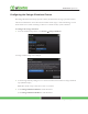
Technician Operations Configuring the Swinger Shutdown Feature The Swinger Shutdown feature helps prevent a runaway TouchScreen from tying up the central station. After the TouchScreen has sent an alarm the set number of times (trips) to central monitoring, no more alarms will be sent to central monitoring for 48 hours or until the security system is disarmed. To configure the swinger shutdown: 1. From the Installer Settings Menu, touch Security ® Swinger Shutdown.
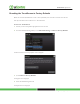
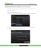
Technician Operations Resetting the TouchScreen to Factory Defaults When an activated TouchScreen is reset to factory defaults, the customer’s account must also be reset by Customer Care in order for it to be reactivated. To reset the TouchScreen: 1. Ensure you have the premise passphrase for the account. 2. From the Installer Settings Menu, touch Advanced Settings ® Reset to Factory Defaults. The Reset Touchscreen to Factory Defaults screen is displayed. 3. Touch Reset to Factory Defaults.
Technician Operations 5. Enter the PREMISE PASSPHRASE for the current account. The device resets and the Installation screen is displayed. 6. To activate the system again: a. Contact Customer Care to have the customer’s account reset. b. Follow the steps starting on page 9 to activate the system again.
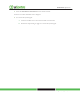
Technician Operations Checking for New Firmware Updates for the TouchScreen You can have a TouchScreen look for an available update on the server or install an update from a USB drive (see page 78). To check for a firmware update on the server: 1. From the Installer Settings Menu, touch Advanced Settings ® Check for Firmware Update. The Checking for Firmware Upgrade screen is displayed.
Technician Operations If a newer firmware version is available for the current device’s hardware version, an Upgrade Firmware button is displayed. 2. Touch Upgrade Firmware to download and install the new firmware version (the system will reboot.
Technician Operations To install a firmware update from a USB drive: Important: The TouchScreen will install an earlier firmware version or even the same firmware version using this method. 1. Save a build image (for example, SMC_P5_19424_ucontrol.upg) to a USB drive in the root directory. 2. Change the filename to ucontrol.upg. 3. Insert the USB drive into the TouchScreen USB port.
Technician Operations Enabling Fire Alarm Verification Fire Alarm Verification causes the system to contact central monitoring when one of the following is true: • Multiple smoke detectors fault • A single smoke detector faults for 60 seconds By default Fire Alarm Verification is disabled: The system immediately sends an alarm to central monitoring when the smoke alarm trips.
Technician Operations The Fire Alarm Settings screen is displayed. 2. Touch Enable to turn Fire Alarm Verification on. 3. Touch Disabled to turn Fire Alarm Verification off.
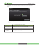
Managing the Physical Devices in Your Security System Managing the Physical Devices in Your Security System The TouchScreen is designed to work with num Table 11: Device Details Device Device Type Batteries Model TouchScreen Central Controller Door/ Window Sensor P5 TS Type 4 volt Lithium Management Instructions Quantity 1 N/A CR2 1 CR123A 3 Glass Break Detector CR123A 1 Smoke/Heat Detector CR123A Key Fob CR2032 2 Page 106 CR2 2 Page 112 Motion Detector Sensor Sensor Key Pad Ca
Managing the Physical Devices in Your Security System Managing Sensors & Zones A sensor is a physical device that detects events in the security system, such as a door opening or movement in a room. A security zone is the representation of a sensor that is being monitored by the TouchScreen.
Managing the Physical Devices in Your Security System To reset a sensor to factory defaults: 1. Delete the associated security zone from the TouchScreen (see page 88). 2. Reset the sensor to factory defaults as described in its installation documentation. 3. Add the sensor again to the TouchScreen (see page 85). To modify the details for a sensor/zone in the security system: 1. From the Installer Settings Menu, touch Sensors & Zones ® Edit a Sensor/Zone.
Managing the Physical Devices in Your Security System The Edit Sensors/Zone—Modify Zone Settings wizard is displayed. 3. Touch a field to change it. Touching menu fields display a menu of items. Touching text fields displays a keyboard screen to change a label. 4. Touch Next to move through the wizard. 5. Touch Return to Menu when the sensor modifications are complete.
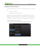
Managing the Physical Devices in Your Security System To add a sensor to the security system: 1. From the Installer Settings Menu, touch Sensors & Zones ® Add a Sensor/Zone. The Locating Wireless Sensors screen is displayed. 2. Ensure each sensor to be added to the TouchScreen is in Search mode. Note 1: See the sensor installation documentation for how to tell if a sensor is in Search mode, it is not in Search mode, and how to restart Search mode if it is not.
Managing the Physical Devices in Your Security System A Stop button is displayed on the Locating Wireless Sensors screen. The TouchScreen searches for sensors that are available to be added. As sensors are found, a grayed icon is displayed for that sensor. 4. Fault each found sensor to pair it to the TouchScreen. For example, for Door/Window sensors, separate the magnet and reed switch to mimic a door being opened. As sensors are found, a grayed icon is displayed for that sensor.
Managing the Physical Devices in Your Security System 7. Click Next. The Configure Wireless Sensors screen is displayed. 8. Touch each sensor icon to configure it. The details that are available for configuration vary based on the type of sensor being configured. See Table 2 on page 25 To modify a text field such as the Zone Label, touch the field to display a keyboard. 9. When all the sensors are properly configured, touch Next in the Configure Wireless Sensors screen.
Managing the Physical Devices in Your Security System To delete a sensor to the security system: 1. Contact Customer Care to get the Premise Passphrase for the current customer’s account. 2. From the Installer Settings Menu, touch Sensors & Zones ® Delete a Sensor/Zone. The Premise Passphrase keyboard screen is displayed. 3. Enter the customer’s Premise Passphrase and touch Done. An icon for each monitored sensor is displayed.
Managing the Physical Devices in Your Security System 4. Touch the sensor icon to delete its sensors. A confirmation dialog is displayed: Deleting a zone cannot be undone. Are you sure you want to delete the zone? 5. Touch Yes. The sensor icon is deleted. The sensor is no longer being monitored by the security system. 6. Fault the sensor to have it reset to factory default and placed in Search mode to be re-added to a TouchScreen. To view details and diagnostic information about a sensor: 1.
Managing the Physical Devices in Your Security System 2. Touch the sensor icon to view its diagnostics. The details about the sensor are displayed. The following information is displayed about the sensor and security zone: § Sensor serial number and type (Door/Window, smoke detector, etc.
Managing the Physical Devices in Your Security System Managing Cross-Zone Associations A cross-zone association requires the following for an alarm to be tripped: • Two specific sensors are faulted • The sensor are faulted in a particular order • The sensors are faulted within a set time period For example, you can require that a door be opened and that a motion sensor detect movement in order for an alarm to be tripped.
Managing the Physical Devices in Your Security System To create a cross-zone association for two sensors: 1. From the Installer Settings Menu, touch Sensors & Zones ® Cross Zone Association. The Cross Zone Associations screen is displayed. 2. Touch Add.
Managing the Physical Devices in Your Security System The Add Cross-Zone Associations screen is displayed. 3. Touch a sensor/security zone listed in the First Zone column. 4. Touch a different sensor/security listed in the Second Zone column. 5. In the Cross Zone Timeout field, touch the arrows to set the number of seconds that the system will wait after ONE of the sensors is faulted to see if the OTHER sensor is faulted. 6. Touch Save to create the cross-zone association.
Managing the Physical Devices in Your Security System The Cross Zone Associations screen is displayed listing each cross-zone association. 2. Touch Delete next to a cross-zone association. The cross-zone association is removed.
Managing the Physical Devices in Your Security System Managing Cameras You can have up to six cameras connected to a TouchScreen at a time. Each camera has a name assigned to it when it is added. Each camera can also be associated with a sensor so that it takes a series of pictures when an alarm is tripped by the sensor. IMPORTANT: The camera images are accessible to the TouchScreen device and (for one of the cameras) to the Subscriber Portal. NOTHING ELSE.
Managing the Physical Devices in Your Security System To add a camera to the security device: 1. From the Installer Settings Menu, touch Cameras ® Add a Camera. The Hardware Setup screen is displayed. 2. Perform the steps described on the Hardware Setup screen. 3. Touch Next.
Managing the Physical Devices in Your Security System The Locating Camera screen is displayed. The system locates the camera that is connected to the TouchScreen’s router with an Ethernet cable, and displays its details. 4. Touch Accept to pair the camera with the Touchscreen. After a few seconds the Configuring Camera field is marked “Done”. 5. Touch Next.
Managing the Physical Devices in Your Security System The Edit New Camera screen is displayed. 6. Touch the Camera Name fields to display a keyboard screen and rename the Camera zone to something that clearly differentiates it from any other cameras. Click Done to accept your changes.
Managing the Physical Devices in Your Security System 7. Touch the Associated Zone field to assign the camera to a security zone. When a camera is assigned to a zone, it takes a series of pictures when an alarm is tripped at that zone. A camera can be assigned to zones for the following types of sensors: door/window sensor, motion detector, glass break detector, smoke detector. See Table 4 on page 43 information about the Associated Zone menu options. 8.
Managing the Physical Devices in Your Security System c. Touch Next to return to the Adjust Camera Video Quality screen. d. Touch the appropriate video quality based on the measured speed, and touch Next. 9. Touch Next. The Camera Wi-Fi Connection Test screen is displayed. 10. Follow the instructions in the Camera Wi-Fi Connection Test screen to have the camera connected to the TouchScreen wirelessly.
Managing the Physical Devices in Your Security System 11. When the camera has been successfully paired wirelessly to the TouchScreen, touch Next. The Adjust Camera screen is displayed. 12. Point the camera as needed. 13. Touch Next. The Add Additional Camera screen is displayed. 14. Touch Add Another to add an additional camera. Repeat steps 2 on page 13. Touch Next to end this operation. If this is the first camera added to the system, the Camera widget is added to the Home screen in the TouchScreen.
Managing the Physical Devices in Your Security System To modify the details of a camera: Use this method to: § Change the name of a camera as it appears in reports on the TouchScreen and in the Subscriber Portal. § Assign, reassign, and unassign a camera to a sensor so that it takes a series of pictures when an alarm is tripped by the sensor 1. From the Installer Settings Menu, touch Cameras ® Edit a Camera.
Managing the Physical Devices in Your Security System The details of the selected camera are displayed. 3. Touch the Camera Name fields to display a keyboard screen and rename the Camera zone. Click Done to accept your changes. Touch the Associated Zone field to display menu of options for assigning the camera to a security zone. See Table 4 on page 43 information about the Associated Zone menu options.
Managing the Physical Devices in Your Security System To replace the camera currently installed in the security system with another camera: 1. Perform the Delete a Camera operation on page 104 for the old camera. 2. Reset the new camera to factory defaults and connect an Ethernet cable to it. 3. Perform the Add a Camera operation on page 96 for the new camera. .To delete a camera attached to the security system: 1. From the Installer Settings Menu, touch Cameras ® Delete a Camera.
Managing the Physical Devices in Your Security System 2. Touch the image for the installed camera. A confirmation message is displayed: Are you sure you want to delete . 3. Touch Yes. The camera image is removed from the Delete a Camera screen.
Managing the Physical Devices in Your Security System Managing Key Fobs A key fob is a mobile device used to quickly arm and disarm the security system. The following operations are used to manage key fobs.
Managing the Physical Devices in Your Security System The Locating Key Fobs screen is displayed. 2. Touch Next to begin searching for key fobs to add. A Stop button is displayed on the Locating Key Fobs screen. The TouchScreen searches for key fobs that are available to be added (defaulted and in Search mode). 3. Default a key fob and place it in Search mode. When a key fob is found, a darkened icon is displayed for it.
Managing the Physical Devices in Your Security System 4. Press the star button to pair the found key fob. The key fob is paired with the TouchScreen and the icon is ungreyed. 5. Touch the key fob icon to configure the name that is used for it in the TouchScreen and Subscriber Portal. 6. Touch Stop. The Wireless Key Fobs Located screen notes the number of key fobs found and paired. 7. Touch Next.
Managing the Physical Devices in Your Security System The Configure Wireless Key Fobs screen is displayed. 8. Touch the key fob icon to configure the name that is used for it in the TouchScreen and Subscriber Portal. To change the name of a key fob: 1. From the Installer Settings Menu, touch Key Fobs & Pads ® Edit Key Fob.
Managing the Physical Devices in Your Security System The Settings screen displays a rectangular icon for each key fob currently added to the system. 2. To modify the system label for the key fob, touch its icon to display a keyboard. 3. Enter a new name and touch Done. 4. Repeat the previous step to modify additional key fobs, or touch Return to Menu to end this operation. To reset a key fob to factory defaults: 1. Delete the associated key fob from the TouchScreen (see the following procedure). 2.
Managing the Physical Devices in Your Security System The Delete a Key Fob screen is displayed with an icon representing each key fob currently installed to the security system. 2. Touch the icon for the key fob to delete. A confirmation message is displayed: Are you sure you want to delete . 3. Touch Yes. The key fob icon is removed from the Delete a Key Fob screen. 4. Touch Yes. 5.
Managing the Physical Devices in Your Security System Managing Key Pads A key pad is a mobile device used to remotely enter key pad codes. Perform the operations in this section to manage key pads as described in this section: • Add • Delete (page 117) • Reset to default (page 117) • Change the name of a key pad as shown in reports on the TouchScreen and in the Subscriber Portal (page 115) These operations are performed from the Installer Settings Menu (see Technician Operations on page 62).
Managing the Physical Devices in Your Security System The Locating Key Pads screen is displayed. 2. Touch Next to begin searching for key fobs to add. A Stop button is displayed on the Locating Key Pads screen. The TouchScreen searches for key pads that are available to be added (defaulted and in Search mode). 3. Default a key pad and place it in Search mode. When a key pad is found, a darkened icon is displayed for it.
Managing the Physical Devices in Your Security System 4. Press the star button to pair the found key pad. The key pad is paired with the TouchScreen and the icon is ungreyed. 5. Touch Stop. The Wireless Key Pads Located screen notes the number of key pads found and paired. 6. Touch Next.
Managing the Physical Devices in Your Security System The Configure Wireless Key Pads screen is displayed. 7. Touch each key pad icon to configure the name that is used for it in the TouchScreen and Subscriber Portal. A keyboard screen is displayed. 8. Enter a name for the key pad, and touch Done to return to the Configure Wireless Key Pads screen. To change the name of a key pad: 1. From the Installer Settings Menu, touch Key Fobs & Pads ® Edit Key Fob.
Managing the Physical Devices in Your Security System The Settings screen displays a rectangular icon for each key pad currently added to the system. 2. To modify the system label for the key pad, touch its icon to display a keyboard. Enter a new name and touch Done.
Managing the Physical Devices in Your Security System 3. Repeat the previous step to modify additional key pads, or touch Return to Menu to end this operation. To reset a key pad to factory defaults: 1. Delete the associated key pad from the TouchScreen (see page 117). 2. Reset the key pad to factory defaults as described in its installation documentation. 3. Add the key pad again to the TouchScreen (see page 112). To delete a key pad from the security system: 1.
Managing the Physical Devices in Your Security System 2. Touch the icon for the key fob to delete. A confirmation message is displayed: Are you sure you want to delete . 3. Touch Yes. The key pad icon is removed from the Delete a Key Fob screen. 4. After deleting the key pad from the TouchScreen, press the button to reset the device to default and place it in Search mode so it can be added to a TouchScreen again.
Managing the Physical Devices in Your Security System Replacing a TouchScreen The Return Merchandise Authorization (RMA) procedure does not involve configuring the customer’s sensors, peripherals, or cameras. This procedure also does not require that the customer reactivate the Subscriber Portal. The zone configuration, key pad codes, configured alerts, images, and any other configurations are retained. The device-swap is seamless from the user point-of-view.
Managing the Physical Devices in Your Security System The System Information screen is displayed. 5. If the current account has not been marked for RMA already, contact Customer Care and request that it be marked for RMA. 6.
Managing the Physical Devices in Your Security System 7. Touch directly on the Broadband Server value (the IP). The Edit System Configuration Information screen is displayed. 8. Change the Broadband Server IP, Cellular Server IP, and the Cellular APN values by touching them to display a keyboard in the screen. Enter the new values and touch Done. 9. After all the values have been set, touch Next. The System Information screen is displayed. 10. Touch Next.
Managing the Physical Devices in Your Security System The Welcome Screen is displayed. 11. Touch Next. The Connectivity screen displays the type of Internet router to which the TouchScreen will connect. 12. Touch the type of router the TouchScreen will use and touch Next.
Managing the Physical Devices in Your Security System The Connectivity Setup screen displays options for connecting to the router/modem. Note: The following options are displayed: § Router — Connect to the router/modem wirelessly) § Ethernet with Router — Connect to the router/modem using an IEEE 802.3 Ethernet cable 13. Touch the method for the TouchScreen to connect to the router/modem and click Next. If Router was selected, the Router Connection Checklist is displayed.
Managing the Physical Devices in Your Security System If Ethernet with Router was selected, the Ethernet Connection Checklist is displayed. 14. Follow the instructions on the Connection Checklist screen. 15. Reset the router/modem to factory defaults and then reboot it. For wireless connectivity: a. Click Next. The TouchScreen locates all the available wireless routers in range, and displays their MAC address.
Managing the Physical Devices in Your Security System b. Check the MAC address for the router/modem to which the TouchScreen must connect (usually located at the back of the device). c. Touch the MAC address for the correct router. d. Touch Next. The Configuring and Securing the Router screen is displayed as the TouchScreen establishes a firm connection with the router/modem, the Broadband servers, and the Cellular connectivity servers.
Managing the Physical Devices in Your Security System For cabled connectivity: a. Click Next. The Ethernet Adapters screen is displayed. The TouchScreen locates and secures the Ethernet adapter. b. Wait a few minutes for the router/modem to reassign IP addresses. Note: If the system cannot find the proper router, ensure it has been reset to factory default. 16. After the TouchScreen successfully establishes its connections, touch Next.
Managing the Physical Devices in Your Security System Note: If the router is connected to the TouchScreen by Ethernet, then Wi-Fi is not tested. 17. Touch Next. The Testing Connectivity screen is displayed. 18. Touch Next.
Managing the Physical Devices in Your Security System The TouchScreen tests it connectivity with the Broadband servers and the Cellular servers (used for alerts when the broadband connection is unavailable). Note: If there is a problem with the connectivity to either type of server, contact Customer Care. 19. When the connectivity test is successful for each, touch Next.
Managing the Physical Devices in Your Security System The TouchScreen checks for a newer firmware version to install. 20. If an upgrade version is available, touch Upgrade Firmware. If an upgrade is not available or after the upgrade is installed, touch Next. The Enter Activation Code keypad is displayed.
Managing the Physical Devices in Your Security System 21. Enter the RMA Activation Code and touch Next. 22. Enter the Account Phone Number and touch Next. The Choose TouchScreen to Replace screen is displayed. 23. Touch the CPE ID of the TouchScreen to be replaced, and then touch Next. The Handling RMA Activation screen is displayed.
Troubleshooting Table 12: General Troubleshooting Aids Problem Cause Solution Firmware Update Problem See Table 10 on page 77. Invalid Code User entered an invalid keypad code. Use the Settings widget to add, edit, and delete keypad codes System not ready to Arm Door or window is open. Open the Security widget and check the security zones, door or window might be open System will not Arm User entered an invalid keypad code when attempting to arm the system Reattempt to enter the security code.
Appendix A: General Concepts of the Security System Arming and Exiting a Premises The Exit Delay period is the amount of time that starts when the security system is armed. The customer has this period of time to exit through an Entry/Exit sensor doorway. If the customer does not exit during this period, the system cannot be armed in Arm Away state. The system will arm in Arm Stay state. The system audibly beeps once per second announcing that the system is in the Exit Delay period.
Appendix A: General Concepts of the Security System Disarming and Entering a Premises The Entry Delay period is the amount of time from an Entry/Exit sensor being faulted until an alarm sounds. The customer has until the end of the Entry Delay period to enter a valid keypad code. There is no Entry Delay period for Perimeter type sensors (such as window sensors or non-entry door sensors). The TouchScreen audibly beeps once per second announcing that the system is in the Entry Delay period.
Appendix A: General Concepts of the Security System The Duress Code The Duress keypad code is used if an intruder forces the customer to disarm her system or access her security settings. Rather than entering her keypad code, she enters the Duress keypad code. When she does this, she is granted full access to her TouchScreen, but a silent alarm is immediately sent to the central monitoring station and police are dispatched.
Appendix B: TouchScreen Placement Options The TouchScreen can be positioned on a flat surface or mounted to the wall (see page 136). Wherever the TouchScreen is placed, ensure that it is in a location where its sirens and other audible signals can be clearly heard by the occupants. Additionally, the TouchScreen should be located where someone entering the premises can easily access it to disarm it. Positioning the TouchScreen on a Flat Surface The TouchScreen can be positioned on a flat surface.
Appendix B: TouchScreen Placement Options Mounting the TouchScreen on the Wall Rather than placing the TouchScreen on a table, desk, or counter, the device can be mounted on the wall using the wall mount.
Appendix B: TouchScreen Placement Options To mount the TouchScreen to the wall: 1. Insert the A/C adapter into the bracket. See Table 1 on page 6 for electrical ratings for the A/C power supply. 2. Remove the center screw from the wall outlet. 3. Plug the TouchScreen’s A/C adapter into the TOP plug of the wall outlet, and replace the center screw through the bracket hole. 4. As shown in Figure 50: a. Cut a hole in the wall near an unswitched wall outlet (not controlled Figure 50 by a light switch). b.
Appendix B: TouchScreen Placement Options 5. Use the included screws to affix the wall mount to the wall over the cut-out (Figure 51). 6. Attach the TouchScreen to the wall mount by aligning the wall mount protuberances to the holes in the back of the TouchScreen (Figure 52). Figure 51 Figure 52 7. After the TouchScreen has been attached to the wall mount, slide it down to secure it in place.
Appendix C: Recommendations for Sensor Installation and Placement Door/Window Sensors and Glass Break Detectors Install door/window sensors and/or glass break detectors at every possible location of entry, both upstairs and down. Glass Break Detectors For best detector performance, select a mounting location that is: § Within 7.6 m (25ft) of the protected glass § Within clear view of the protected glass § On the same wall as the protected glass § At least 2 m (6.
Appendix C: Recommendations for Sensor Installation and Placement Motion Detectors When placing motion detectors, anticipate traffic patterns: § The lanes of traffic most used by people in your home are also those most likely to be used by intruders § Foyers, stairways, hallways, and entrance-ways are excellent locations for a motion detector. § Do not place motion detectors at the end of hallways where an intruder will be walking directly toward or away from the detector.
Appendix C: Recommendations for Sensor Installation and Placement Smoke Detector Installation Recommendations The National Fire Protection Association (NFPA) recommends the following for the number and placement of smoke detectors. Place smoke alarms as follows: § In every bedroom, in hallways, and on every level of the premises, including the attic and basement.
Appendix C: Recommendations for Sensor Installation and Placement § DO NOT install near areas fresh air inlets or returns or excessively drafty areas. Heating/ A/C vents, fans, and fresh air intakes can drive smoke away from smoke detectors. § Remember that dead air spaces may prevent smoke from reaching a smoke detector. Camera Installation Recommendations Camera views are accessible to TouchScreen users and family members who log into the Subscriber Portal.
Appendix D: Using the Key Pad Appendix D: Using the Key Pad A key pad is a wireless peripheral that lets you perform certain TouchScreen functions in additional locations in your premises. For example, you could install a key pad near a less-used entry or in an upstairs bedroom to ensure its Emergency Alarm feature is always readily accessible.
Appendix D: Using the Key Pad Arming the System From the key pad, you can arm your system in Arm Away mode or Arm Stay. Arm Night mode must be performed from the TouchScreen or Subscriber Portal. Arm Away Mode Enter a valid keypad code followed by the button to arm the system in Arm Away mode (no one still in the premises). See the TouchScreen User Guide for an explanation of this arming mode.
Appendix D: Using the Key Pad Sending an Emergency Police Alarm Press and hold this button for about 2 seconds to send a silent alarm to central monitoring for police assistance. This Disarm works the same as though you performed this operation from the TouchScreen. The button flashes red to indicate that the alarm has been sent. The TouchScreen will not react in any way but if you check the History tab on the Security widget, you are able to see that an alarm was sent.
Appendix D: Using the Key Pad Changing the Batteries in the Key Pad To replace the batteries in the key pad: 1. With a Phillips screwdriver, remove the screw from the battery cover in the back of the key pad and remove the cover. 2. Find the two supplied CR2 3-volt lithium batteries and install them positive end up. 3. Replace the battery cover.
Appendix E: Using the Key Fob A key fob is a wireless peripheral that lets you remotely perform certain TouchScreen functions anywhere within RF range of the TouchScreen, including outside the premises.
Appendix E: Using the Key Fob Arming the System From the key pad, you can arm your system in Arm Away mode or Arm Stay. Arm Night mode must be performed from the TouchScreen or Subscriber Portal. Arm Away Mode Press the button for 1.5 seconds to arm the system in Arm Away mode (no one still in the premises). See the TouchScreen User Guide for an explanation of this arming mode. The LED flashes red once to indicate that it has contacted the system then lights red for one second.
Appendix E: Using the Key Fob Sending an Emergency Police Alarm Press and hold the button for 2.25 seconds to send a silent alarm to central monitoring for police assistance. The LED flashes orange to indicate that the alarm has been sent. The TouchScreen will not react in any way, but if you check the History tab on the Security widget, you are able to see that an alarm was sent. Additionally, Contact persons will receive email and SMS notifications if they are configured to do so.