ROBO Cylinder Rod Type RCS2 Actuators Motor Straight Type (Coupling Type): RA4C, RA5C, RGS4C, RGS5C, RGD4C and RGD5C Motor Straight Type (Built-in Type): RA4D, RA7AD, RA7BD, RGS4D and RGS7AD RGS7BD, RGD4D, RGD7AD and RGD7BD Motor Reversing Type: RA4R and RA5R Flat Type F5D RCS2W Actuators, Dustproof/Splash-proof Specification Motor Straight Type (Coupling Type): RA4C Motor Straight Type (Built-in Type): RA4D Motor Reversing Type: RA4R Operating Manual Third Edition IAI America, Inc.
Safety Precautions (Please read before using the product.) Before installing, operating, maintaining or inspecting this product, please peruse this operating manual as well as the operating manuals and other related documentations for all equipment and peripheral devices connected to this product in order to ensure the correct use of this product and connected equipment/devices.
z Avoid using the product in a place where the main unit or controller may come in contact with water or oil droplets. z Never cut and/or reconnect the cables supplied with the product for the purpose of extending or shortening the cable length. Doing so may result in fire. [Operation] z Do not enter the machine’s range of operation while the product is operating or standing by. The actuator may move suddenly, causing injury. z Do not pour water onto the product.
z Do not step on the product, use it as a footstool or place any object on it. You may slip and fall or the product may tip over or drop, resulting in injury. Malfunction, runaway product, etc., may also result due to product breakdown or damage. [Maintenance, Inspection, Repair] z Before commencing maintenance/inspection, servicing, replacement or any other work on the product, be sure to completely cut off the power supply to the product. Also take heed of the following precautions: 1.
[Operation] z Turn on the power to individual equipment one by one, starting from the equipment at the highest level in the system hierarchy. Failure to do so may cause the product to start suddenly, resulting in injury or product damage. z Do not insert a finger or object in the openings in the product. It may cause fire, electric shock or injury. z Do not step on the product, use it as a footstool or place any object on it.
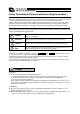
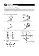
Prohibited Handling of Cables When designing an application system using IAI’s actuators and controllers, incorrect wiring or connection of each cable may cause unexpected problems such as a disconnected cable or poor contact, or even a runaway system. This section explains prohibited handling of cables. Read the information carefully to connect the cables properly. 1. Do not let the cable flex at a single point. Steel band (piano wire) Bundle loosely. 2. Do not let the cable bend, kink or twist. 3.
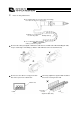
. Notes on using cable bearers z The supplied cables are not robot cables. Accordingly, never store the cables in a cable bearer. z Always use a robot cable for each relay cable. Bending radius (r) z Use a cable bearer with a bending radius (r) of 50 mm or greater. z Do not let the cable get tangled or kinked in a cable bearer or flexible tube. When bundling the cable, keep a certain degree of flexibility (so that the cable will not become too taut when bent).
Table of Contents 1. Foreword ............................................................................................................................................ 1 2. Safety Precautions ............................................................................................................................. 1 2.1 Basic Operating Instructions ...........................................................................................1 2.2 Maintenance and Inspection ................................
. Connecting the Air Tube of the RCS2W Dustproof/Splash-proof Type........................................... 28 10. Maximum Speed ............................................................................................................................ 29 11. Load on the Actuator ...................................................................................................................... 30 12. Actuators with a Switch (Optional) ..................................................................
1. Foreword Thank you for purchasing an IAI product. This manual explains the structure, correct operation and maintenance of the actuator. Please read this manual carefully before using the product. For more complete information on operating the actuator, please also refer to the controller operating manual. 2. Safety Precautions 2.1 Basic Operating Instructions • Please do not attempt to use or operate the actuator in any manner not indicated in this manual or the controller manual.
3. Warranty 3.1 Warranty Period Warranty period shall be either of the following periods whichever ends first: • 18 months after shipment from our factory • 12 months after delivery to a specified location • 2500 hours of operation time 3.2 Scope of Warranty If a breakdown occurs within the period specified above and is due to the manufacturer's error, we will repair the unit at no cost. However, the following items are not covered by this warranty.
4. Names of the Parts The names of the actuator parts are indicated below. In this manual, the right and left are determined by viewing the actuator from the top and from the motor side. 4.1 Motor Straight Type (Coupling Type): No Guide z RCS2-RA4C Right Rod side Motor side Left Head cover Rod Rod cover Cylinder tube Motor unit Rod tip adapter Cable Caution: The cable directly connected to the actuator is not robot cable even when ordered with robot cable option.
4.2 Motor Straight Type (Built-in Type): No Guide z RCS2-RA4D Right Rod side Motor side Left Rod Rod cover Cylinder tube Head cover Motor unit Rod tip adapter Cable Caution: 4 The cable directly connected to the actuator is not robot cable even when ordered with robot cable option. When designing, please be sure not to give repeated bending loads to this cable. The robot cable is applicable only to the connecting cables.
4.3 Motor Reversing Type: No Guide z RCS2-RA4R Right Rod side Motor side Left Cable Motor unit Pulley case Rod tip adapter Rod Caution: Rod cover Cylinder tube Head cover The cable directly connected to the actuator is not robot cable even when ordered with robot cable option. When designing, please be sure not to give repeated bending loads to this cable. The robot cable is applicable only to the connecting cables.
4.4 Motor Straight Type (Coupling Type): Single-guide Type z RCS2-RGS4C Right Rod side Motor side Guide bracket Guide bearing Left Guide rod Head cover Motor unit Rod Rod cover Cylinder tube Cable Caution: 6 The cable directly connected to the actuator is not robot cable even when ordered with robot cable option. When designing, please be sure not to give repeated bending loads to this cable. The robot cable is applicable only to the connecting cables.
4.5 Motor Straight Type (Coupling Type): Double-guide Type z RCS2-RGD4C Guide bracket Guide bearing Guide rod Head cover Motor unit Right Motor side Rod side Rod Left Rod cover Cylinder tube Cable Caution: The cable directly connected to the actuator is not robot cable even when ordered with robot cable option. When designing, please be sure not to give repeated bending loads to this cable. The robot cable is applicable only to the connecting cables.
The names of respective actuator parts are indicated below. In this manual, the right and left are determined by viewing the actuator from the top and from the motor side when the actuator is placed horizontally. “Front” indicates the opposite side of the motor. 4.6 Motor Straight Type (Coupling Type): No Guide z RCS2-RA5C Right Front Motor side Left Connector box Aluminum frame Rod Rod tip adapter Motor housing 4.
4.8 Motor Straight Type (Coupling Type): Single-guide Type z RCS2-RGS5C Guide bearing Guide rod 4.
4.10 Short Type z RCS2-RA7A(B)D Right Front Motor side Anti-vibration screws (4 locations) Never touch these screws. Left Connector box Aluminum frame Rod tip adapter Encoder cover Motor housing 4.
4.12 Dustproof/Splash-proof Motor Straight Type (Coupling Type) z RCS2W-RA4C Right Rod side Motor side Left Bellows Intake/ exhaust port Rod Cylinder tube Rod cover Head cover Motor unit Rod tip adapter Cable Caution: The cable directly connected to the actuator is not robot cable even when ordered with robot cable option. When designing, please be sure not to give repeated bending loads to this cable. The robot cable is applicable only to the connecting cables.
5. Transporting and Handling 5.1 Handling the Actuator 5.1.1 Handling the Packed Unit Unless otherwise specified, each actuator (axis) is shipped individually. Please take care that the shipping box is not dropped or subjected to strong impact during transport. • • • • The operator should not carry heavy shipping boxes by themselves. If the shipping box is left standing, it should be in a horizontal position. Do not climb on top of the shipping box. Do not place heavy objects on top of the shipping box.
5.2 Handling the Actuator Assembly Pay attention to the following instructions when transporting an assembly of actuator axes. 5.2.1 Condition of Shipment from IAI (Assembled) The actuators you have ordered are assembled at IAI, after which the assembly receives a shipping inspection and is shipped in an outer frame with skids. The assembly is packed with the rod securely affixed so that it will not move unexpectedly during transportation.
6. Operating and Storage Environment 6.1 Operating Environment The actuator should be set up in an environment, which meets the following criteria: • • • • • • • • • • • Avoid direct sunlight. Avoid radiant heat from strong heat sources such as a furnace. Ambient temperature should be 0 ~ 40°C. The humidity should be less than 85% and there should be no condensation. Avoid exposure to corrosive or combustible gases. The area should have very little dust and be suitable for normal assembly operations.
7. Installation 7.1 Installing the Main Body (1) Using screws on the rod or head side Install the actuator using screws set on the rod or head side of the actuator. z Applicable model: RCS2-RA4 Straight type MA Rod cover Cylinder tube Head cover MB Reversing type Motor unit Pulley case MA MA Rod Rod cover Type RA4 type Cylinder tube MA M30 x 1.5 Head cover MB M40 x 1.
(2) Using screws on a flange (optional) An optional flange is available for installing the actuator. Use this flange, if necessary. z Applicable model: RCS2-RA4 Straight type Mounting hole Affixing nut Flange Straight type Mounting hole Affixing nut Flange Screw size Tightening torque 16 Mating material is steel M6 12.3 N-m Mating material is aluminum M6 5.
Reversing type Affixing nut Mounting hole Flange Reversing type Affixing nut Mounting hole Flange Screw size Tightening torque Mating material is steel M6 12.3 N-m Mating material is aluminum M6 5.
(3) Using screws on feet (optional) Optional feet are available for installing the actuator. Use these feet, if necessary. z Applicable model: RCS2-RA4 Straight type Mounting hole Affixing nut Affixing nut Mounting hole Foot B Foot A Mounting hole Mounting hole Reversing type Affixing nut Foot Foot Screw size Tightening torque Caution: 18 Affixing nut Mating material is steel M6 12.3 N-m Mating material is aluminum M6 5.
(4) Using screws on a trunnion (optional) An optional trunnion is available for installing the actuator. Use this trunnion, if necessary. z Applicable model: RCS2-RA4 Straight type Mounting hole Affixing nut Trunnion ring Bracket B Bracket A Straight type Mounting hole Trunnion ring Affixing nut Bracket B Bracket A Screw size Tightening torque Mating material is steel M6 12.3 N-m Mating material is aluminum M6 5.
Trunnion ring Reversing type Mounting hole Affixing nut Bracket B Bracket A Screw size Tightening torque 20 Mating material is steel M6 12.3 N-m Mating material is aluminum M6 5.4 N-m Caution: Exercise caution when installing the actuator horizontally using the optional clevis or trunnion or any commercially available free joint, because the rod will receive the actuator weight. As a result, the bush may wear quickly or internal mechanical parts may be damaged.
(5) Using screws on a clevis (optional) An optional clevis is available for installing the actuator. Use this clevis, if necessary.
(6) Using screws on a rear mounting bracket (optional) An optional rear mounting bracket is available for installing the actuator. Use this rear mounting bracket, if necessary. z Applicable model: Motor reversing type RA4R Reversing type Tapped mounting hole Type RA4 type 22 Tapped hole diameter M4 Tapped depth 7 mm Tightening torque 1.
(7) Double-guide type Use the tapped holes in the bracket for installing an actuator of the double-guide type. z Applicable model: Double-guide type RGD4 Tapped mounting hole Bracket A Type RA4 type Bracket B Tapped hole diameter M5 Tapped depth 8 mm Tightening torque 3.
(8) Single-guide type Use the tapped holes in the bracket for installing an actuator of the single-guide type. z Applicable model: Double-guide type RGD4 Tapped mounting hole Bracket A Bracket B Type RA4 type 24 Tapped hole diameter M5 Tapped depth 8 mm Tightening torque 3.
(9) Using tapped mounting holes at the back Applicable model: RA7 (excluding 50-mm stroke models) The RA7 type has tapped mounting holes at the back. Use these holes to install the actuator. RA7 Shown below is the maximum screw-in depth of the tapping screws used for mounting the base. Be careful not to allow the tip of the bolt to project.
(11) Using feet Applicable models: RA5, RA5R, RA7 (excluding flat types) [1] On the RA7 type, attach feet using the tapped [2] mounting holes at the back. On the RA5 type, attach feet using square nuts inserted into the T-grooves. Foot Foot Install the feet to the frame using bolts.
8. Wiring Cable • In an application where the cable cannot be anchored, try to place the cable so that it sags only under its own weight or use self-standing type cable as large radial wire duct to limit the load on the cable. • Never cut and/or reconnect the cables supplied with the product for the purpose of extending or shortening the cable length. • The cables supplied with the actuator offer excellent flexibility, but they are not robot cables.
9. Connecting the Air Tube of the RCS2W Dustproof/Splash-proof Type Intake/exhaust port Install the air tube (outer diameter: 10 mm, inner diameter: 6.5 mm) on the intake/exhaust port and guide the air tube to a location where the external environment assures the tube will not come in contact with water.
10. Maximum Speed The maximum speed of the actuator is limited to prevent resonance of the ball screw shaft and also in consideration of the restrictions on motor speed. Observe the maximum speed limits specified below.
11. Load on the Actuator • The actual load should not exceed the value specified in the catalog. • Be sure to align the shaft center of the rod and the moving direction of the load. • Lateral load may cause damage or breakdown of the actuator. • If the rod may receive lateral load, provide a guide or other appropriate mechanism to support the actuator in the moving direction of the load. • Do not allow the rod (slide shaft) to receive rotational torque. * Doing so may damage the internal parts.
13. High Acceleration/Deceleration Option 13.1 Applicable Actuator Models Actuators that support high acceleration/deceleration are indicated by an option code at the end of the model name. Other applicable options are the same as those available with conventional models.
13.3 Notes Take note of the following points if you are using a high acceleration/deceleration type: (1) Keep the duty within 50%. If the duty exceeds 50%, an overload error may occur. (2) The maximum loading capacity follows the applicable value specified in the table under “Specifications of High acceleration/Deceleration Actuators” regardless of the acceleration setting. (3) Refer to p. 29 for the maximum speed. 13.
14. Maintenance 14.1 Maintenance Schedule Perform maintenance work according to the schedule below. The schedule is set assuming eight hours of operation a day. When the operation time is long such as 24-hour operation, shorten the maintenance intervals as needed.
14.4 Applying Grease to the Sliding Surface of the Rod (1) Applicable grease Kyodo Yushi Multemp LRL3 Warning: Never use any fluorine-based grease. It will cause a chemical reaction when mixed with a lithium-based grease and may cause damage to the actuator. (2) How to apply grease Apply grease over the entire surface of the rod.
14.5 Reduction Belt [Motor Reversing Type] 14.5.1 Inspecting the Belt Remove the pulley cover and visually inspect the belt. Durability of the reduction belt is affected significantly by the operating condition, and there is no standard guideline as to when the belt should be replaced. Generally, the belt is designed to withstand several millions of flexing loads.
14.5.3 Adjusting the Belt Tension (RA4R Type) Remove the pulley case cover and loosen the four motor-unit affixing bolts. Pass a looped string (or long tie-band) around the motor unit, and pull the string to the specified tension using a tension gauge. In this condition, uniformly tighten the motor-unit affixing bolts. [Recommended tightening torque of adjustment bolts] 162 N-cm (16.5 kgf-cm) Tension: 2.5 kgf Motor-unit affixing bolts (Use an Allen wrench of 2.5 mm across flats.
14.5.4 Adjusting the Belt Tension (RA5R) Remove the pulley case cover and loosen the four motor-unit affixing bolts. Pass a looped string (or long tie-band) around the motor unit, and pull the string to the specified tension using a tension gauge. In this condition, uniformly tighten the motor-unit affixing bolts. [Recommended tightening torque for adjustment bolts] Tension: 6 ± 0.2 kgf Motor-unit affixing bolts (Use an Allen wrench of 3 mm across flats.
14.5.5 Replacing the Belt of the Motor Reversing Type: RA4R Type [Items Required for Replacement] • Replacement belt RA4R --- 60S2M152R Rubber, cleanroom type (Bando Chemical Industries) 6 mm wide • Allen wrenches • Tension gauge (capable of tensioning to 7 kgf or greater) • Strong string, looped (or long tie-band) • Scale • Oil-based marker pen • PC or teaching pendant [Overview of Replacement] 1) Move the rod to a position where Z phase turns on (home position) (2 mm from the mechanical end).
[Procedure] 1) Remove the pulley case cover using two Allen wrenches, one of 2 mm across flats and the other of 3 mm across flats. M4 hexagon socket head screws M3 hexagon socket head screws 2) Move the rod to a position where Z phase turns on (home position). This corresponds to a position where the rod projects 2 mm from the mechanical end. Apply countermarks in this position. Cause the rod to project 2 mm from the mechanical end.
3) Loosen the motor-unit affixing bolts using an Allen wrench of 2.5 mm across flats. Slide the motor, and loosen and remove the belt. Motor-unit affixing bolts (Use an Allen wrench of 2.5 mm across flats.) Motor-unit affixing bolts (Use an Allen wrench of 2.5 mm across flats.) 4) Check the following points before restoring the home position: • The motor side should be aligned with the initial countermark. If the position is offset, adjust it to achieve proper alignment.
5) Adjust the belt tension. Pass a looped strong string (or long tie-band) around the motor cover and pull it with a tension gauge to the specified tension. In this condition, uniformly tighten the motor-unit affixing bolts. [Recommended tightening torque for adjustment bolts] 162 N-cm (16.5 kgf-cm) Tension: 2.5 kgf Motor-unit affixing bolts (Use an Allen wrench of 2.5 mm across flats.) Motor-unit affixing bolts (Use an Allen wrench of 2.5 mm across flats.
6) Install the pulley case cover using two Allen wrenches, one of 2 mm across flats and the other of 3 mm across flats. M4 hexagon socket head screws M3 hexagon socket head screws 7) Connect a PC or teaching pendant to the controller to perform homing. (If the actuator is of absolute encoder specification, an absolute reset must be performed.) Check for deviation from the initial home position. If there is a deviation, adjust parameter No. 22, “Home offset” if you are using an SCON controller.
14.5.6 Replacing the Belt of the Motor Reversing Type: RA5R Type [Items Required for Replacement] • Replacement belt RA5R ---100S3M219R Rubber, cleanroom type (Bando Chemical Industries) 10 mm wide • Allen wrenches • Tension gauge (capable of tensioning to 8 kgf or greater) • Strong string, looped (or long tie-band) • Scale • Oil-based marker pen • PC or teaching pendant [Overview of Replacement] 1) Move the rod to a position where Z phase turns on (home position) (2 mm from the mechanical end).
[Procedure] 1) Move the slider from the home position toward the mechanical end and check the rotating direction of the motor shaft. (If the actuator has its home located on the opposite side to the standard specification, this check is always required because the motor shaft rotates in the different direction.) • Remove the pulley case cover. (Remove the three thin-head screws using an Allen wrench of 2.5 mm across flats.) Check the rotating direction of the motor shaft.
4) Adjust the belt tension. Pass a looped strong string (or long tie-band) around the motor cover and pull it with a tension gauge to the specified tension. In this condition, uniformly tighten the motor-unit affixing bolts. Recommended tightening torque for adjustment bolts: (M5) 763 N-cm (78 kgf-cm) Caution: After tightening the bolts to the above torque, tighten them slightly further by making sure that both pulleys do not move. Tension: 6 ± 0.2 kgf 5) Install the pulley cover.
14.6 Replacing the Motor 14.6.1 Replacing the Motor of the Motor Straight Type (Coupling Type): RA4C Type [Items Required for Replacement] • Replacement motor unit • Coupling (with screws) • Allen wrenches • Scale • Oil-based marker pen • Grease Idemitsu Kosan Replacement motor unit Daphne Eponex Grease No.2 • PC or teaching pendant Coupling (with screws) [Overview of Replacement] 1) Move the rod to a position where Z phase turns on (home position) (2 mm from the mechanical end).
[Procedure] 1) Move the rod to a position where Z phase turns on (home position). This corresponds to a position where the rod projects 2 mm from the mechanical end. Apply countermarks in this position. Cause the rod to project 2 mm from the mechanical end. 2 mm Apply countermarks once the rod has projected 2 mm from the mechanical end. Warning: If the actuator is installed vertically, move it after turning on the controller power and forcibly releasing the brake.
3) Pull out the motor unit. Before pulling out the motor unit, apply a countermark on the cylinder tube at a position corresponding to the tab on the motor unit, so that the motor unit and cylinder can be aligned in the correct position later on. Tab on the motor unit Apply a countermark at a position corresponding to the tab on the motor unit. 4) Apply grease on the actuator coupling. Apply grease on the inside of the coupling.
5) Align the tab on the replacement motor unit with the countermark on the cylinder. With the motor unit and cylinder aligned properly, insert the coupling into the replacement motor unit by aligning the orientation of this coupling with that of the actuator coupling (adjusted to a position corresponding to a rod projection of 2 mm from the mechanical end). Apply countermarks to identify the current motor position (phase Z position) and coupling.
6) Turn the coupling and motor shaft simultaneously until a setscrew on the coupling is seen through the hole. Thereafter, tighten the hexagon socket head setscrew using an Allen wrench of 2 mm across flats. Similarly, turn the coupling and motor shaft simultaneously until the other screw is seen through the hole, and tighten the setscrew. Coupling setscrew hole 50 Turn the coupling and motor shaft simultaneously until a setscrew on the coupling is seen through the hole.
7) Return the coupling in the replacement motor unit to the initial motor position (Z phase position). Align the tab on the replacement motor unit with the countermark on the cylinder. With the motor unit and cylinder positioned this way, confirm that the orientation of the actuator coupling (adjusted to a position corresponding to a rod projection of 2 mm from the mechanical end) corresponds to the position of the coupling in the replacement motor unit.
8) Carefully insert the replacement motor unit into the cylinder by ensuring that the couplings do not lose their alignment. 9) Using an Allen wench of 2 mm across flats, tighten the two motor-unit affixing bolts on the right and left. 2 affixing bolts on the motor-end cap (right and left) (hexagon socket head setscrews) 10) Connect a PC or teaching pendant to the controller to perform homing. (If the actuator is of absolute encoder specification, an absolute reset must be performed).
14.6.2 Replacing the Motor of the Motor Reversing Type: RA4R Type [Items Required for Replacement] • Replacement motor unit • Allen wrenches • Tension gauge (capable of tensioning to 7 kgf or greater) • Strong string, looped (or long tie-band) • Scale • Oil-based marker pen • PC or teaching pendant Replacement motor unit [Overview of Replacement] 1) Loosen the motor-unit affixing bolts to remove the belt, and replace the motor. 2) Restore the home position.
[Procedure] 1) Remove the pulley case cover using two Allen wrenches, one of 2 mm across flats and the other of 3 mm across flats. M4 hexagon socket head screws M3 hexagon socket head screws 2) Loosen the motor-unit affixing bolts using an Allen wrench of 2.5 mm across flats. Slide the motor, and loosen and remove the belt. After the belt has been removed, remove the motor-unit affixing bolts. Motor-unit affixing bolts (Use an Allen wrench of 2.5 mm across flats.
3) Take out the motor. 4) Install the replacement motor. Loosely tighten the motor-unit affixing bolts.
5) Move the rod to a position where Z phase turns on (home position). This corresponds to a position where the rod projects 2 mm from the mechanical end. Apply countermarks in this position. Cause the rod to project 2 mm from the mechanical end. 2 mm Apply countermarks once the rod has projected 2 mm from the mechanical end. Warning: If the actuator is installed vertically, move it after turning on the controller power and forcibly releasing the brake.
7) Adjust the belt tension. Pass a looped strong string (or long tie-band) around the motor cover and pull it with a tension gauge to the specified tension. In this condition, uniformly tighten the motor-unit affixing bolts. [Recommended tightening torque for adjustment bolts] 162 N-cm (16.5 kgf-cm) Tension: 2.5 kgf Motor-unit affixing bolts (Use an Allen wrench of 2.5 mm across flats.) Motor-unit affixing bolts (Use an Allen wrench of 2.5 mm across flats.
8) Remove the pulley case cover using two Allen wrenches, one of 2 mm across flats and the other of 3 mm across flats. M4 hexagon socket head screws M3 hexagon socket head screws 9) Connect a PC or teaching pendant to the controller to perform homing. (If the actuator is of absolute encoder specification, an absolute reset must be performed.) Check for deviation from the initial home position. If there is a deviation, adjust parameter No. 22, “Home offset” if you are using an SCON controller.
14.6.3 Replacing the Motor of the Motor Reversing Type: RA5R Type [Items Required for Replacement] • Replacement motor with pulleys (See the photograph to the right.) (Confirm that the motor has countermarks.
[Procedure] 1) Move the slider from the home position toward the mechanical end and check the rotating direction of the motor shaft. (If the actuator has its home located on the opposite side to the standard specification, this check is always required because the motor shaft rotates in the different direction.) • Remove the pulley case cover. (Remove the three thin-head screws using an Allen wrench of 2.5 mm across flats.) Check the rotating direction of the motor shaft.
5) Make the following adjustment to restore the home position: • Move the slider to the mechanical end on the home side and keep it in contact with the mechanical end. • Turn the motor shaft by the specified amount from the countermark position toward the return-tomechanical-end direction (the direction checked at the beginning). Type Amount returned from the countermark position RA5R-16 67.5° RA5R-8 135° RA5R-4 230° 6) Adjust the belt tension.
14.7 Replacing the Bellows of the RCS2W Dustproof/Splash-proof Type Bellows [Items Required for Replacement] • Replacement bellows unit : RA4 --- JB-RA4- (stroke) • Phillips screwdriver • Torque driver • Grease Kyodo Yushi Multemp LRL3 [Procedure] 1) Loosen the front and rear metal fittings affixing the bellows and remove the bellows.
2) Apply grease evenly over the entire cylinder surface. Apply grease evenly over the entire surface. 3) Install a metal fitting on the bellows. Install a metal fitting on the bellows.
4) Install the replacement (new) bellows and tighten the screws of the front and rear metal fittings affixing the bellows. Tighten the screws to the specified torque using a torque driver.
15. Cable Drawings [1] Motor cable/robot motor cable Model: CB-RCC-MA /CB-RCC-MA (20) (21) (9 ∅) L (10) 1 (41) (18) 4 (21) (16) -RB (Front view) 1 (Front view) 4 Actuator end Controller end Wire 0.75 sq Signal PE No. 1 U 2 2 U V V W 3 4 3 4 W PE No. 1 Signal Wire 0.
[2] Encoder cable/robot encoder cable (X-SEL-J/K) (SCON, SSEL, X-SEL-P/Q) Model: CB-RCBC-PA /CB- RCBC-PA (16) L (14) (36) (57) (15) (33) (25) (8 ∅) 1.10 (Front view) 9.18 (Front view) Controller end Wire Signal A/U A/U B/V B/V Z/W 0.15 sq (crimped) Z/W SD SD BAT + BAT VCC GND BK BK + - Actuator end No. 1 2 3 4 5 6 7 8 9 10 11 12 13 14 15 Clamp the shield to the hood. Ground and shielded braided wires 66 No.
[3] Encoder cable/robot encoder cable Model: CB-RCS2-PA /CB- X2-PA -RB L (41) (14) (15) (13) (25) (37) 1.10 1 14 26 13 (Front view) F Wire Color - Signal - E24V OV Brown/white LS CLEEP OT RSV Gray/white AWG26 (soldered) Blue/red Actuator end Controller end - Pink Purple White Blue/red - Blue Orange Black Yellow Green Brown Gray Red A+ AB+ BZ+ ZSRD + SRD BAT + BAT VCC GND BKR BKR + - - Orange/white Green/white Clamp the shield to the hood. Note 3 9.18 (Front view) No.
MEMO 68
Catalog No.: MJ3656-3A Head Office: 2690 W. 237th Street, Torrance, CA 90505 TEL (310) 891-6015 FAX (310) 891-0815 Chicago Office: 1261 Hamilton Parkway, Itasca, IL 60143 TEL (630) 467-9900 FAX (630) 467-9912 Atlanta Office: 1220-E Kenneston Circle, Marietta, GA 30066 TEL (678) 354-9470 FAX (678) 354-9471 Website: www.intelligentactuator.