INSTALLATION GUIDE ta SMC8126PL2-F TigerSwitchTM 10/100/1000 L2-Lite SMB PoE Gigabit Switch
TigerSwitch 10/100/1000 Installation Guide From SMC's Tiger line of feature-rich workgroup LAN solutions 20 Mason Irvine, CA 92618 Phone: (949) 679-8000 September 2009 Pub.
Information furnished by SMC Networks, Inc. (SMC) is believed to be accurate and reliable. However, no responsibility is assumed by SMC for its use, nor for any infringements of patents or other rights of third parties which may result from its use. No license is granted by implication or otherwise under any patent or patent rights of SMC. SMC reserves the right to change specifications at any time without notice. Copyright © 2009 by SMC Networks, Inc. 20 Mason Irvine, CA 92618 All rights reserved.
Warranty and Product Registration To register SMC products and to review the detailed warranty statement, please refer to the Support Section of the SMC Website at http://www.smc.com.
Compliances and Safety Warnings FCC - Class A This equipment has been tested and found to comply with the limits for a Class A digital device, pursuant to part 15 of the FCC Rules. These limits are designed to provide reasonable protection against harmful interference when the equipment is operated in a commercial environment.
CE Mark Declaration of Conformance for EMI and Safety (EEC) This information technology equipment complies with the requirements of the Council Directive 89/336/EEC on the Approximation of the laws of the Member States relating to Electromagnetic Compatibility and 73/23/EEC for electrical equipment used within certain voltage limits and the Amendment Directive 93/68/EEC.
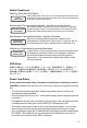
Safety Compliance Warning: Fiber Optic Port Safety CLASS I LASER DEVICE When using a fiber optic port, never look at the transmit laser while it is powered on. Also, never look directly at the fiber TX port and fiber cable ends when they are powered on. Avertissment: Ports pour fibres optiques - sécurité sur le plan optique DISPOSITIF LASER DE CLASSE I Ne regardez jamais le laser tant qu'il est sous tension.
France and Peru only This unit cannot be powered from IT† supplies. If your supplies are of IT type, this unit must be powered by 230 V (2P+T) via an isolation transformer ratio 1:1, with the secondary connection point labelled Neutral, connected directly to earth (ground). Important! Before making connections, make sure you have the correct cord set. Check it (read the label on the cable) against the following: Power Cord Set U.S.A. and Canada The cord set must be UL-approved and CSA certified.
• L’appareil fonctionne à une tension extrêmement basse de sécurité qui est conforme à la norme IEC 60950. Ces conditions ne sont maintenues que si l’équipement auquel il est raccordé fonctionne dans les mêmes conditions. France et Pérou uniquement: Ce groupe ne peut pas être alimenté par un dispositif à impédance à la terre.
• Este equipo opera bajo las condiciones SELV (Safety Extra Low Voltage o Voltaje extra bajo de seguridad) de acuerdo con la norma IEC 60950. Las condiciones sólo se mantienen si la equipo al cual está conectado también opera bajo condiciones SELV. Francia y Perú únicamente Este equipo no puede ser energizado desde suministros IT†.
Bitte unbedingt vor dem Einbauen des Switches die folgenden Sicherheitsanweisungen durchlesen: WARNUNG: Die Installation und der Ausbau des Geräts darf nur durch Fachpersonal erfolgen. • Das Gerät sollte nicht an eine ungeerdete Wechselstromsteckdose angeschlossen werden. • Das Gerät muß an eine geerdete Steckdose angeschlossen werden, welche die internationalen Sicherheitsnormen erfüllt.
Advertencias y mensajes de precaución Advertencia: Este producto no contiene ninguna pieza reparable por el usuario. Advertencia: La instalación y remoción del equipo sólo debe ser llevada a cabo por personal calificado. Advertencia: Cuando enchufe este aparato a un tomacorriente, conecte el cable de tierra del enchufe tripolar a una línea válida de tierra física para prevenir riesgos de tipo eléctrico.
Purpose This guide details the hardware features of the switches, including their physical and performance-related characteristics, and how to install each switch. Audience This guide is for system administrators with a working knowledge of network management. You should be familiar with switching and networking concepts. Esta guía es para los administradores de sistemas que cuenten con conocimientos básicos de gestión de redes.
x
Contents Chapter 1: Introduction Overview Switch Architecture Power-over-Ethernet Capability Network Management Options Description of Hardware 10/100/1000BASE-T Ports SFP Slots Port and System Status LEDs Mode PoE/Link Button Optional Redundant Power Unit Power Supply Socket Features and Benefits Connectivity Expandability Performance Management Chapter 2: Network Planning Introduction to Switching Application Examples Collapsed Backbone Network Aggregation Plan Remote Connections with Fiber Cable Making
Contents Connecting to the Console Port Wiring Map for Serial Cable Chapter 4: Making Network Connections Connecting Network Devices Twisted-Pair Devices Cabling Guidelines Connecting to PCs, Servers, Hubs and Switches Network Wiring Connections Fiber Optic SFP Devices Connectivity Rules 1000BASE-T Cable Requirements 1000 Mbps Gigabit Ethernet Collision Domain 100 Mbps Fast Ethernet Collision Domain 10 Mbps Ethernet Collision Domain Cable Labeling and Connection Records 3-6 3-7 4-1 4-1 4-1 4-1 4-2 4-2 4-3
Contents Appendix D: Ordering Information D-1 Appendix E: Spanish Instructions E-1 Selección de un sitio Montaje en bastidor E-1 E-1 Glossary Index xiii
Tables Table 1-1 Table 1-2 Table 3-1 Table 4-1 Table 4-2 Table 4-3 Table 4-4 Table 4-5 Table 4-6 Table A-1 Table B-1 Table B-2 Table B-3 Table D-1 xiv Port Status LEDs System Status LEDs Serial Cable Wiring Maximum 1000BASE-T Gigabit Ethernet Cable Length Maximum 1000BASE-SX Gigabit Ethernet Cable Length Maximum 1000BASE-LX Gigabit Ethernet Cable Length Maximum 1000BASE-ZX Gigabit Ethernet Cable Length Maximum Fast Ethernet Cable Length Maximum Ethernet Cable Length Troubleshooting Chart 10/100BASE-TX MDI
Figures Figure 1-1 Figure 1-2 Figure 1-3 Figure 1-4 Figure 1-5 Figure 1-6 Figure 2-1 Figure 2-2 Figure 2-3 Figure 2-4 Figure 3-1 Figure 3-2 Figure 3-3 Figure 3-4 Figure 3-5 Figure 3-6 Figure 3-7 Figure 4-1 Figure 4-2 Figure 4-3 Figure B-1 Figure B-2 Figure B-3 Figure E-1 Figure E-2 Front Panel Rear Panel Port LEDs System LEDs Mode Selection Power Supply Socket Collapsed Backbone Network Aggregation Plan Remote Connections with Fiber Cable Making VLAN Connections RJ-45 Connections Attaching the Brackets Ins
xvi
Chapter 1: Introduction Overview The TigerSwitch 10/100/1000, SMC8126PL2-F, is an intelligent Layer 2 switch with 26 10/100/1000BASE-T ports, four of which are combination ports* that are shared with four SFP transceiver slots (see Figure 1-1, Ports 21-24). The switch’s 24 10/100/1000 Mbps ports support the IEEE 802.3af Power-over-Ethernet (PoE) standard that enables DC power to be supplied to attached devices over wire pairs in the connecting Ethernet cable.
1 Introduction Switch Architecture The SMC8126PL2-F employs a wire-speed, non-blocking switching fabric. This permits simultaneous wire-speed transport of multiple packets at low latency on all ports. It also features full-duplex capability on all ports, which effectively doubles the bandwidth of each connection. This switch uses store-and-forward switching to ensure maximum data integrity.
Description of Hardware 1 Description of Hardware 10/100/1000BASE-T Ports The SMC8126PL2-F contains 26 RJ-45 ports that operate at 10 Mbps or 100 Mbps, half or full duplex, or at 1000 Mbps, full duplex. Because all ports on this switch support automatic MDI/MDI-X operation, you can use straight-through cables for all network connections to PCs or servers, or to other switches or hubs. (See "1000BASE-T Pin Assignments" on page B-3.
1 Introduction Table 1-1 Port Status LEDs Label Color Description Port 1-24 (Link/Activity/ Speed Mode) On/Flashing Amber Port has a valid link at 10 or 100 Mbps. Flashing indicates activity. On/Flashing Green Port has a valid link at 1000 Mbps. Flashing indicates activity. Off There is no valid link on the port. Port 1-24 (PoE Mode) On Amber A PoE device is connected. Off No PoE device connected. Port 21/22/23/ On Green 24 Off Port 25/26 SFP transceiver plugged in.
Description of Hardware 1 Mode PoE/Link Button The Mode PoE/Link button is located on the front panel. Mode Select Button Figure 1-5 Mode Selection The Mode PoE/Link button is used to toggle between the two port status LED display modes (see "Port and System Status LEDs" on page 1-3). Pressing this button changes from one display mode to the other. The default display mode is Link/Act/Speed mode.
1 Introduction Features and Benefits Connectivity • 26 10/100/1000 Mbps ports for easy Gigabit Ethernet integration and for protection of your investment in legacy LAN equipment. • Auto-negotiation enables each RJ-45 port to automatically select the optimum communication mode (half or full duplex) if this feature is supported by the attached device; otherwise the port can be configured manually. • RJ-45 10/100/1000BASE-T ports support auto MDI/MDI-X pinout selection.
Chapter 2: Network Planning Introduction to Switching A network switch allows simultaneous transmission of multiple packets via non-crossbar switching. This means that it can partition a network more efficiently than bridges or routers. These switches have, therefore, been recognized as one of the most important building blocks for today’s networking technology.
2 Network Planning Application Examples The SMC8126PL2-F is not only designed to segment your network, but also to provide a wide range of options in setting up network connections. Some typical applications are described below. Collapsed Backbone The SMC8126PL2-F is an excellent choice for mixed Ethernet, Fast Ethernet, and Gigabit Ethernet installations where significant growth is expected in the near future.
Application Examples 2 Network Aggregation Plan With 26 parallel bridging ports (i.e., 26 distinct collision domains), a switch can collapse a complex network down into a single efficient bridged node, increasing overall bandwidth and throughput. In the figure below, the 10/100/1000BASE-T ports are providing 1000 Mbps connectivity through Layer 2 switches. In addition, the switches are also connecting several servers at 1000 Mbps. Server Farm 10/100/1000 Mbps Segments ... ...
2 Network Planning Remote Connections with Fiber Cable Fiber optic technology allows for longer cabling than any other media type. A 1000BASE-SX (MMF) link can connect to a site up to 550 meters away, a 1000BASE-LX (SMF) link up to 5 km, and a 1000BASE-ZX link up to 100 km. This allows a switch to serve as a collapsed backbone, providing direct connectivity for a widespread LAN.
Application Examples 2 Making VLAN Connections This switch support VLANs which can be used to organize any group of network nodes into separate broadcast domains. VLANs confine broadcast traffic to the originating group, and can eliminate broadcast storms in large networks. This provides a more secure and cleaner network environment. VLANs can be based on untagged port groups, or traffic can be explicitly tagged to identify the VLAN group to which it belongs.
2 Network Planning Application Notes 1. Full-duplex operation only applies to point-to-point access (such as when a switch is attached to a workstation, server or another switch). When the switch is connected to a hub, both devices must operate in half-duplex mode. 2. For network applications that require routing between dissimilar network types, you can attach these switches directly to a multi-protocol router. 3.
Chapter 3: Installing the Switch Selecting a Site The SMC8126PL2-F can be mounted in a standard 19-inch equipment rack or on a flat surface. Be sure to follow the guidelines below when choosing a location. • The site should: - be at the center of all the devices you want to link and near a power outlet.
3 Installing the Switch RJ-45 Connector Figure 3-1 RJ-45 Connections Equipment Checklist After unpacking the switch, check the contents to be sure you have received all the components. Then, before beginning the installation, be sure you have all other necessary installation equipment.
Mounting 3 Mounting This switch can be mounted in a standard 19-inch equipment rack or on a desktop or shelf. Mounting instructions for each type of site follow. Rack Mounting Before rack mounting the switch, pay particular attention to the following factors: • Temperature: Since the temperature within a rack assembly may be higher than the ambient room temperature, check that the rack-environment temperature is within the specified operating temperature range. (See page C-1.
3 2. Installing the Switch Mount the device in the rack, using four rack-mounting screws (not provided). Figure 3-3 Installing the Switch in a Rack 3. If installing a single switch only, turn to "Connecting to a Power Source" at the end of this chapter. 4. If installing multiple switches, mount them in the rack, one below the other, in any order. Desktop or Shelf Mounting 1. Attach the four adhesive feet to the bottom of the first switch. Figure 3-4 Attaching the Adhesive Feet 2.
Installing an Optional SFP Transceiver 3 3. If installing a single switch only, go to "Connecting to a Power Source" at the end of this chapter. 4. If installing multiple switches, attach four adhesive feet to each one. Place each device squarely on top of the one below, in any order. Installing an Optional SFP Transceiver Figure 3-5 Inserting an SFP Transceiver into a Slot The switch supports 1000BASE-SX and 1000BASE-LX, and 1000BASE-ZX SFP-compatible transceivers.
3 Installing the Switch Connecting to a Power Source To connect a device to a power source: 1. Insert the power cable plug directly into the socket located at the back of the device. Figure 3-6 Power Socket 2. Plug the other end of the cable into a grounded, 3-pin, AC power source. Note: For international use, you may need to change the AC line cord. You must use a line cord set that has been approved for the receptacle type in your country. 3.
Connecting to the Console Port 3 Wiring Map for Serial Cable Table 3-1 Serial Cable Wiring Switch’s 8-Pin Serial Port Null Modem PC’s 9-Pin DTE Port 6 RXD (receive data) <---------------------------- 3 TXD (transmit data) -----------------------------> 2 RXD (receive data) 3 TXD (transmit data) 5 SGND (signal ground) ------------------------------ 5 SGND (signal ground) No other pins are used.
3 3-8 Installing the Switch
Chapter 4: Making Network Connections Connecting Network Devices The SMC8126PL2-F is designed to interconnect multiple network segments (or collision domains). It can be connected to network cards in PCs and servers, as well as to hubs, switches or routers. It may also be connected to devices using optional SFP transceivers. Twisted-Pair Devices Each device requires an unshielded twisted-pair (UTP) cable with RJ-45 connectors at both ends.
4 Making Network Connections Connecting to PCs, Servers, Hubs and Switches 1. Attach one end of a twisted-pair cable segment to the device’s RJ-45 connector. Figure 4-1 Making Twisted-Pair Connections 2. If the device is a PC card and the switch is in the wiring closet, attach the other end of the cable segment to a modular wall outlet that is connected to the wiring closet. (See "Network Wiring Connections" on page 4-2.) Otherwise, attach the other end to an available port on the switch.
Fiber Optic SFP Devices 4 Equipment Rack (side view) Network Switch w it c h 10 /1 0 0 6724L3 ES4524C Punch-Down Block Patch Panel Wall Figure 4-2 Network Wiring Connections Fiber Optic SFP Devices An optional Gigabit SFP transceiver (1000BASE-SX, 1000BASE-LX or 1000BASE-ZX) can be used for a backbone connection between switches, or for connecting to a high-speed server. Each single-mode fiber port requires 9/125 micron single-mode fiber optic cable with an LC connector at both ends.
4 Making Network Connections Nota: Cuando seleccione un dispositivo SFP de fibra óptica, y teniendo en cuenta la seguridad, asegúrese de que el mismo pueda operar a una temperatura que no sea mayor que la temperatura máxima recomendada de operación del producto. Se deberá asimismo utilizar un transceptor SFP láser clase 1 aprobado. 1. Remove and keep the LC port’s rubber cover. When not connected to a fiber cable, the rubber cover should be replaced to protect the optics. 2.
Connectivity Rules 4 1000BASE-T Cable Requirements All Category 5 UTP cables that are used for 100BASE-TX connections should also work for 1000BASE-T, providing that all four wire pairs are connected. However, it is recommended that for all critical connections, or any new cable installations, Category 5e (enhanced Category 5) or Category 6 cable should be used. The Category 5e specification includes test parameters that are only recommendations for Category 5.
4 Making Network Connections 10 Mbps Ethernet Collision Domain Table 4-6 Maximum Ethernet Cable Length Type Cable Type Maximum Length Connector 10BASE-T Twisted Pair, Categories 3, 4, 5 or better 100-ohm UTP 100 m (328 ft) RJ-45 Cable Labeling and Connection Records When planning a network installation, it is essential to label the opposing ends of cables and to record where each cable is connected.
Appendix A: Troubleshooting Diagnosing Switch Indicators Table A-1 Troubleshooting Chart Symptom Action Power LED is Off • Check connections between the switch, the power cord, and the wall outlet. • Contact your dealer for assistance. Power LED is Amber • Internal power supply or RPU has failed. System is being powered by connected RPU. Contact your local dealer for assistance. Power LED Flasing Amber • RPU has failed.
A Troubleshooting Installation Verify that all system components have been properly installed. If one or more components appear to be malfunctioning (such as the power cord or network cabling), test them in an alternate environment where you are sure that all the other components are functioning properly. In-Band Access You can access the management agent in the switch from anywhere within the attached network using Telnet, a Web browser, or other network management software tools.
Appendix B: Cables Twisted-Pair Cable and Pin Assignments For 10/100BASE-TX connections, the twisted-pair cable must have two pairs of wires. For 1000BASE-T connections the twisted-pair cable must have four pairs of wires. Each wire pair is identified by two different colors. For example, one wire might be green and the other, green with white stripes. Also, an RJ-45 connector must be attached to both ends of the cable. Caution: DO NOT plug a phone jack connector into any RJ-45 port.
B Cables Table B-1 10/100BASE-TX MDI and MDI-X Port Pinouts Pin 1 MDI Signal Name Transmit Data plus (TD+) MDI-X Signal Name Receive Data plus (RD+) 2 Transmit Data minus (TD-) Receive Data minus (RD-) 3 Receive Data plus (RD+) Transmit Data plus (TD+) 6 Receive Data minus (RD-) Transmit Data minus (TD-) 4,5,7,8 Not used Not used Note: The “+” and “-” signs represent the polarity of the wires that make up each wire pair.
Twisted-Pair Cable and Pin Assignments B You must connect all four wire pairs as shown in the following diagram to support Gigabit Ethernet connections.
B Cables Cable Testing for Existing Category 5 Cable Installed Category 5 cabling must pass tests for Attenuation, Near-End Crosstalk (NEXT), and Far-End Crosstalk (FEXT). This cable testing information is specified in the ANSI/TIA/EIA-TSB-67 standard. Additionally, cables must also pass test parameters for Return Loss and Equal-Level Far-End Crosstalk (ELFEXT).
Fiber Standards B Table B-3 Fiber Standards ITU-T Standard Description Application G.653 Dispersion-Shifted Fiber Single-mode, 9/125-micron core Longer spans and extended reach. Optimized for operation in the region from 1500 to 1600-nm. G.654 1550-nm Loss-Minimized FiberSingle-mode, 9/125-micron core Extended long-haul applications. Optimized for high-power transmission in the 1500 to 1600-nm region, with low loss in the 1550-nm band. G.
B B-6 Cables
Appendix C: Specifications Physical Characteristics Ports 22 10/100/1000BASE-T, with auto-negotiation 4 10/100/1000BASE-T shared with 4 SFP transceiver slots Network Interface Ports 1-26: RJ-45 connector, auto MDI/X 10BASE-T: RJ-45 (100-ohm, UTP cable; Category 3 or better) 100BASE-TX: RJ-45 (100-ohm, UTP cable; Category 5 or better) 1000BASE-T: RJ-45 (100-ohm, UTP or STP cable; Category 5, 5e, or 6) *Maximum Cable Length - 100 m (328 ft) Buffer Architecture 0.
C Specifications AC Input 100 to 240 V, 50-60 Hz, 8.
Standards C Standards IEEE 802.3-2005 Ethernet, Fast Ethernet, Gigabit Ethernet Full-duplex flow control IEEE 802.3af-2003 IEEE 802.3at draft IEEE 802.1D Spanning Tree Protocol IEEE 802.1w Rapid Spanning Tree Protocol IEEE 802.1s Multiple Spanning Tree Protocol IEEE 802.1Q Virtual LAN ISO/IEC 8802-3 CSMA/CD Compliances CE Mark Emissions FCC Class A Industry Canada Class A EN55022 (CISPR 22) Class A EN 61000-3-2/3 Immunity EN 61000-4-2/3/4/5/6/8/11 Safety UL/CUL (UL60950-1, CSA 22.2 No.
C C-4 Specifications
Appendix D: Ordering Information Table D-1 TIgerSwitch 10/100/1000 Products and Accessories Product Number SMC8126PL2-F Description L2-Lite SMB PoE Gigabit Switch D-1
D D-2 Ordering Information
Glossary 10BASE-T IEEE 802.3 specification for 10 Mbps Ethernet over two pairs of Category 3, 4, or 5 UTP cable. 100BASE-TX IEEE 802.3u specification for 100 Mbps Fast Ethernet over two pairs of Category 5 or better UTP cable. 1000BASE-LX IEEE 802.3z specification for Gigabit Ethernet over two strands of 50/125, 62.5/125 or 9/125 micron core fiber cable. 1000BASE-SX IEEE 802.3z specification for Gigabit Ethernet over two strands of 50/125 or 62.5/125 micron core fiber cable. 1000BASE-T IEEE 802.
Glossary CSMA/CD CSMA/CD (Carrier Sense Multiple Access/Collision Detect) is the communication method employed by Ethernet, Fast Ethernet, or Gigabit Ethernet. End Station A workstation, server, or other device that does not forward traffic. Ethernet A network communication system developed and standardized by DEC, Intel, and Xerox, using baseband transmission, CSMA/CD access, logical bus topology, and coaxial cable. The successor IEEE 802.
Glossary IEEE 802.3z Defines CSMA/CD access method and physical layer specifications for 1000BASE Gigabit Ethernet. (Now incorporated in IEEE 802.3-2005.) LAN Segment Separate LAN or collision domain. LED Light emitting diode used for monitoring a device or network condition. Local Area Network (LAN) A group of interconnected computer and support devices.
Glossary Transmission Control Protocol/Internet Protocol (TCP/IP) Protocol suite that includes TCP as the primary transport protocol, and IP as the network layer protocol. UTP Unshielded twisted-pair cable. Virtual LAN (VLAN) A Virtual LAN is a collection of network nodes that share the same collision domain regardless of their physical location or connection point in the network.
Index Numerics 100 Mbps connectivity rules 4-5 1000 Mbps connectivity rules 4-5 1000BASE-LH fiber cable lengths 4-5 1000BASE-LX fiber cable lengths 4-5 1000BASE-SX fiber cable lengths 4-5 1000BASE-T pin assignments B-3 ports 1-2, 1-3 100BASE-TX cable lengths 4-5 ports 1-2, 1-3 10BASE-T ports 1-2, 1-3 10BASE-T/100BASE-TX pin assignments B-1 A accessories, ordering D-1 adhesive feet, attaching 3-4 air flow requirements 3-1 applications collapsed backbone 2-2 network aggregation 2-3 remote connections 2-4 VLA
Index M management agent 1-2 features 1-6, C-2, C-3 out-of-band 1-2 SNMP 1-2 web-based 1-2 mounting the switch on a desktop or shelf 3-4 multimode fiber optic cables 4-3 compliances C-3 environmental C-1 physical C-1 standards, IEEE C-3 status LEDs 1-3 surge suppressor, using 3-1 switch architecture 1-2 switching, introduction to 2-1 T network connections 4-1 examples 2-2 troubleshooting in-band access A-2 power and cooling problems A-1 switch indicators A-1 Telnet A-2 twisted-pair connections 4-1 O V
SMC8126PL2-F 150200062800A R01 150200000032A R02 20 Mason • Irvine, CA 92618 • Phn: 949-679-8000 • www.smc.